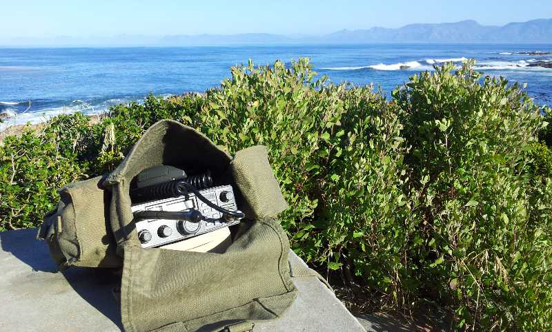
The FT-290R is a mobile 2m all-mode transceiver that can also run off internal batteries for portable use -- an electric handbag, so to speak.
Mine was cheap because the display is broken. This is not unusual.
But! I reverse-engineered the display and designed a replacement. Here's me replacing ZS5DF's display.
The FT-690R and FT-290R have whip antennas, and an SO-239 on the back panel. The FT-790R has a BNC on the front panel only.
In an article A New Life for the FT-290R Transceiver published in HAM-MAG March 2009, F5RCT notes that removing the internal antenna and improving the filter will improve the receive loss by 2dB and the transmit loss by 1.9dB.
One can then choose to use the rear SO-239 or to install a BNC on the front panel. And I hate SO-239s.
F5RCT recommends fitting a series diode instead of the shunt you will find next to J05 on the schematic. I disagree. Or rather, I tend to favour his second recommendation -- the problem is that the shunt diode is on the wrong side of the fuse. If you add a shunt diode on the other side of the fuse, the fuse will blow. Well, hopefully. Use a beefy diode. The fuse is rated at 1.5A.
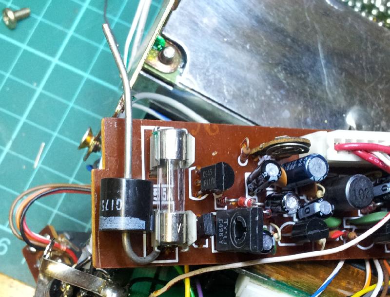
This ia a GI750 6A diode.
The series approach is safer, but the diode drop is a problem. Back in the day we would use a small relay, with the coil connected to the supply via a diode. The correct polarity turns the relay on, the incorrect polarity doesn't. These days, use a FET.
Like your vintage Macintosh, your eighties era radio caps are also leaking by now. Best replace them all.
There are two types of regulator PCBs, the earlier one uses an ICL7660 and the later uses two transistors.
Work in progress:
| Refdes | Value | Location | Notes |
|---|---|---|---|
| C11 | 1000u 16V | Chassis | Replace with 25V |
| C1097 | 0.1u 50V | Main PCB | Replace with 100n X7R ceramic |
|
C1042, C1067, C1086, C1097, C1111, C1112, C1126, C1129, C3027 | 1u 50V | Main PCB | |
| C2001, C2005, C2006, C2013 | 1u 50V | Main PCB | Replace with 100n X7R ceramic (New Life mod) |
| C1092, C1094, C1131, C3048 | 4.7u 25V | Main PCB | |
|
C1062, C1064, C1087, C1104, C2011, C2019, C2021, C2022, C2023, C2086, C2089, C2093, C2096, C2109, C2110, C3010, C3045, C3054, C3055 | 10u 16V | Main PCB | |
| C2004 | 10u 16V | Main PCB | Replace with 100n X7R ceramic (New Life mod) |
| C2007 | 10u 16V | Main PCB | Replace with 1u 50V (New Life mod) |
| C1132 | 47u 16V | Main PCB | |
| C1128, C1137 | 47u 10V | Main PCB | |
| C1134 | 100u 16V | Main PCB | |
| C1136 | 1000u 16V | Main PCB | |
| C4006, C4010 | 0.47u 50V | Regulator Unit | Replace with X7R |
| C4004, C4005 | 1u 50V | Regulator Unit | |
| C4011, C4015 | 10u 16V | Regulator Unit | |
| C4008, C4014 | 47u 10V | Regulator Unit | |
| C4015 | 10u 10V | Regulator Unit (7660) | |
| C4014 | 47u 10V | Regulator Unit (7660) | |
| C4017, C4019, C4020 | 10u 10V | Regulator Unit (two transistor) | |
| C5003, C5004 | 10u 16V | Control Unit |
I like 105C capacitors, also these days you'll find that a 25V capacitor is the same size the 16V used to be, so rather use that.
This is also the perfect time to replace the battery with a CR2032 in a holder from an old PC motherboard. Strangely enough, my original battery still measures over 3V, so I'm not doing that for now.
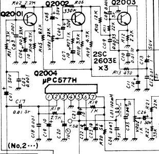
The FT-x90 has two completely separate microphone amplifiers. The microphone is connected to the SSB amp (top) via C01 (1u) and to the FM amp via C17 (0.01u).
The FM mic amp is a UPC577H which is supposed to be an RF amp but it works so who knows. CTCSS is injected at the T.SQ testpoint so of course it doesn't end up in the SSB signal. There is a provision for connecting a CTCSS board (P05) on the schematic but so far I've not been able to locate it in the rig.
G7AQA fits a CTCSS board to his FT-290R.
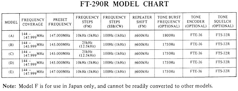
I found two tables of the jumper settings for the various frequency ranges. They are both wrong.
The table by F1GAN only has two errors, the other one has more.
--------------------------------------------------------------------------
     *    *        140-150        25      1000           5MHz
                                 100       100
--------------------------------------------------------------------------
*    *    *    *   140-150         5      1000     no shift possible
                                  10      100
--------------------------------------------------------------------------
Table by ZS1KE 2015-11-07
0 = Jumper not present, 1 = jumper present.
CPU pin 41 40 39 38 - This is the opposite of the other tables out there
                      but it gives a nice grouping.

        Start   Step      Range        Shift
0 0 0 0                                        Garbage
0 0 0 1                                        Garbage
0 0 1 0                                        Garbage
0 0 1 1 3.4000  25 100    0.000-9.999  7.6MHz  FT-790R B
0 1 0 0 3.4000  25 100    0.000-9.999  1.6MHz  FT-790R C
0 1 0 1 6.0000  25 100    0.000-9.999    5MHz  FT-790R A
0 1 1 0 3.0000  10 100    0.000-9.999    5MHz  FT-790R F
0 1 1 1 0.0000  20  10    0.000-3.990    1MHz  FT-690R
1 0 0 0 5.0000  25  12.5  4.000-7.999  600kHz  FT-290R C
1 0 0 1 5.0000  25  12.5  4.000-5.999  600kHz  FT-290R B
1 0 1 0 5.0000  10   5    4.000-7.999  600kHz  FT-290R D
1 0 1 1 5.0000  20  10    4.000-8.999  600kHz  FT-290R
1 1 0 0 5.0000  20  10    4.000-5.999  600kHz  FT-290R
1 1 0 1 7.0000  10   5    3.500-8.499  600kHz  FT-290R
1 1 1 0 7.0000  10   5    4.000-7.999  600kHz  FT-290R A,E (Model A uses 7.3728 MHz crystal to get 1800 Hz tone)
1 1 1 1                                        Garbage
The settings above which give 1.6MHz, 5MHz and 7.6MHz repeater offset are for the FT-790 (70cm) version of this set. The FT-290R and FT-690R are compatible (same IF, same divider values) but the FT-790R is completely different, the VCO is multiplied by three before mixing, which means that a 1 kHz tuning step needs a 1/3 kHz VCO step, which means that using the FT-790R jumper settings on one of the other two rigs will lead to madness (The FT-290R and FT-690R divider runs from 200 to 599 (10kHz steps), I think the FT-790R divider runs from 498 to 1500 (3.3kHz steps, x3)).
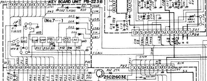
There are jumpers on the keyboard PCB to configure the T CALL button to do something else. Unfortunately what it does is to reset the frequency to 145.000 (Well, I guess to the startup frequency). I don't find this that useful. There is however a mod to listen on the repeater input:
LISTEN ON INPUT

Place the set with controls towards you, remove the bottom cover and locate the
black/white wire on SK1. It's the tenth one from the left. Cut this wire at the
socket and insulate the free end. Locate the green/white wire on SK1 and solder
the anode of a 1N4148 diode to it. Connect the cathode of the diode to the red/
white wire on the PCB adjacent to the mic. socket. Insulate the diode leads to
prevent shorts. When the call button is pressed, it allows listen on input on
both +shift and -shift. When you want the rig to transmit a tone burst you must
close the PTT at the same time as pressing the call button.
This is a rather terrible write-up of a really clever hack.
The black/white wire on SK1 is at least identified as the tenth one from the left. SK1 in this instance is the plug to the regulator unit, called P4 on the schematic, and the wire in question is TCSW, which keys the transmitter when you press the T CALL button. So far so good.
The only green/white wire I can find is on J02 on the processor board. It's on pin 1, PTT, which is grounded on transmit via a diode D26.
So I get it. The idea is to tell the processor that you want to transmit, so that it re-programs the PLL to the input frequency -- without actually going into transmit. The cut wire and D26 will prevent the RF bits from switching over to transmit, so you will still be receiving.
As I said, very clever. Once you figure out that the reference to SK1 is wrong.
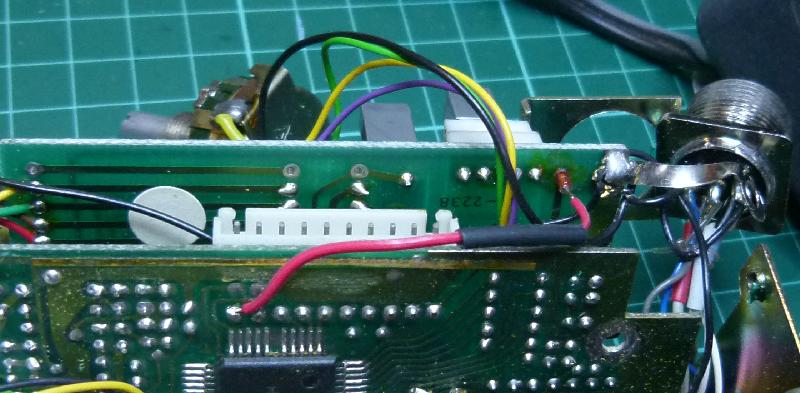
Of course I have no need for tone call, with or without the PTT pressed, so I just unsoldered the T.CALL wire from the switch PCB and wired the diode to the processor board.
(FTS-32E)
|
|
Back | (This page last modified 2023-12-30) |