<- Back root
Reverse-Engineering the Yaesu FT-290R, FT-690R and FT-790R Display
|
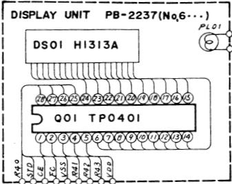
The display schematic looks remarkably like an
HD 44780 in 4-wire
mode. No, I don't think I can substitute an HD 44870! But the interface is TTL, not LCD. I
can therefore put a PIC or something in there, wire it to any display I like, and make it work.
The manual for the KDK
FM-2033 states that "4bit parallel data from the CPU, STD, CE and the framing clock
signals from IC2-1/IC2-2 are applied to LCD driver, TP0401 to dynamically drive the 5 digit LCD,
LD-200". That's about as much as you will find on the 'net, even
Texas Instruments doesn't seem to know
more.
Some inspection of the schematic shows that FC is a free running clock, VDD is 5V and VSS is not
zero, but some voltage which is temperature dependent. This leaves CE, STD and R40 to R43. Four
bits of data, Chip Enable and STore Data? Time to find out.
|
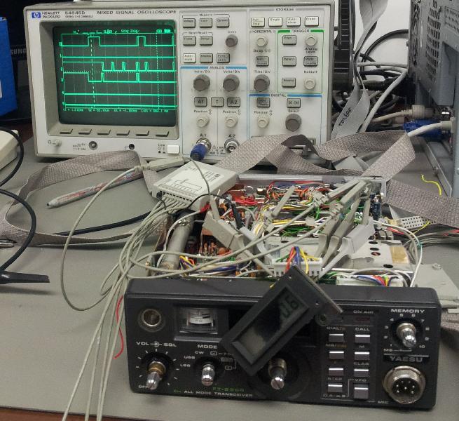
At work I have access to this awesome
HP 54645D oscilloscope which makes
this kind of thing a half-hour task. I expected something esoteric but hey! It's
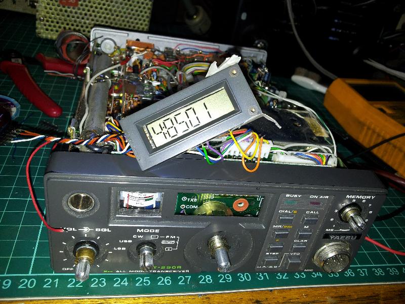
ASCII (well, sort of). Six bytes get
clocked in (by STD), four bits at a time. One byte per digit, the last byte for M, - and CLAR.
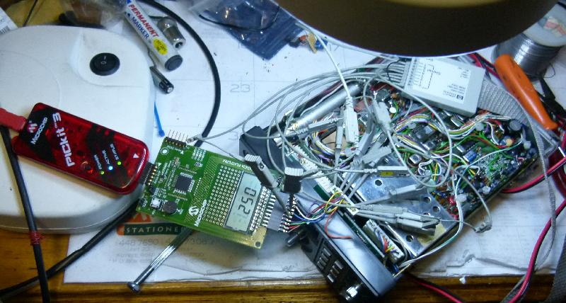
I used an F1 evaluation board* for proof of concept. Things didn't go well until I remembered
to crank the clock up to 32MHz. Now we just need more digits.
* Unfortunately the F1 LCD is too big with too few digits to use for production.
There we go. More digits.
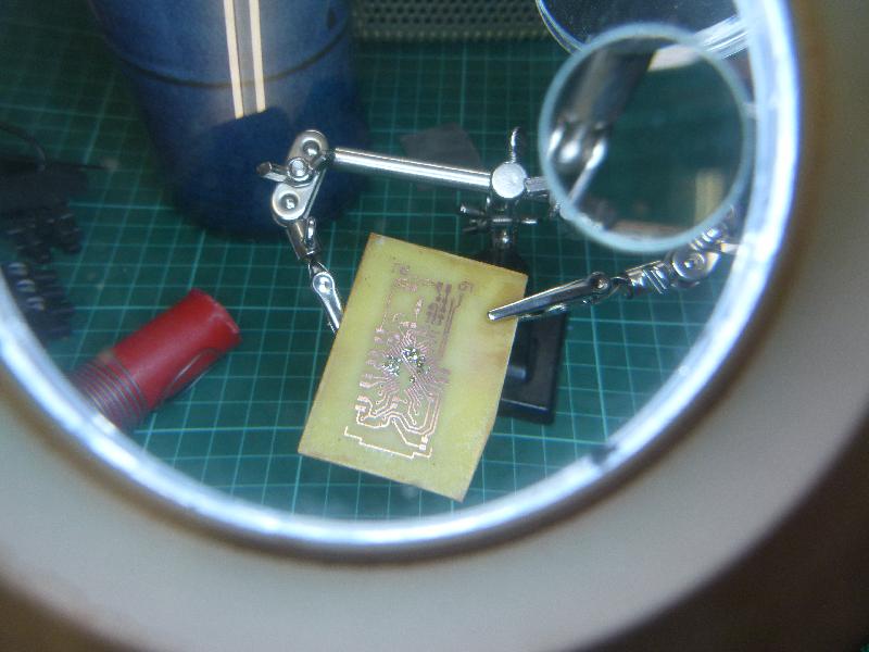
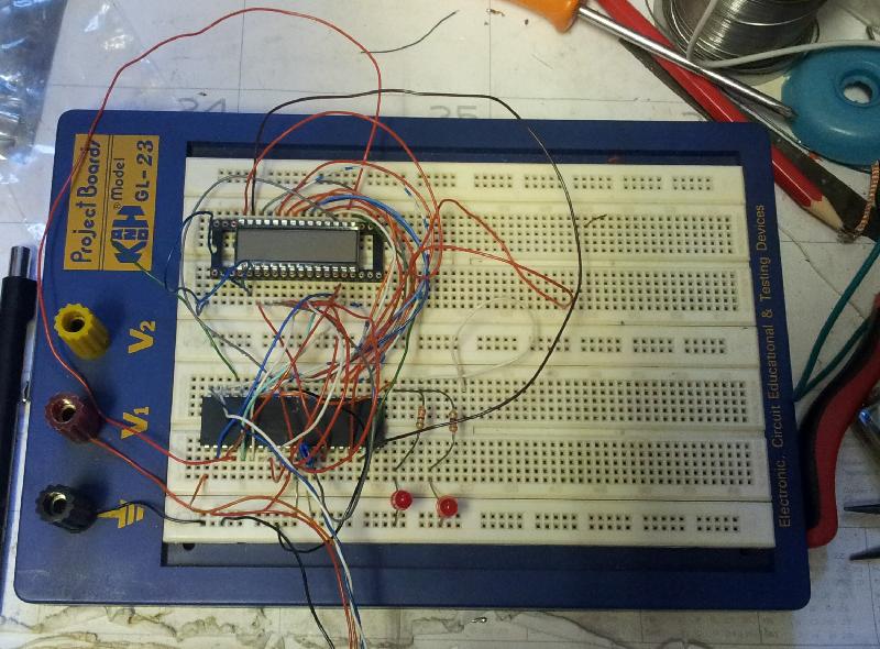
I designed the PCB using Eagle and Reg ZS1ADC made it using the laser printer method. Which is
amazing, considering the line width and the fact that it's double-sided.
You need a magnifying glass for this kind of work. Being a home-made PCB, I have to jumper the vias
from one side of the PCB to the other.
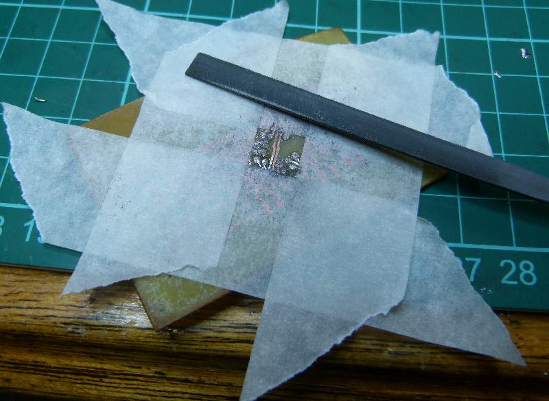
And then I filed the joints down because the chip has to be as close as possible to the PCB.
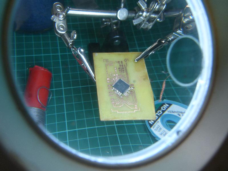
I found the easy way to solder the processor was to not care about solder bridges...
... and to then wick the excess solder with desoldering braid.
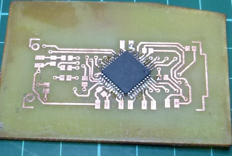
Looking good.
|
![[Image] Hit Count](/cgi-bin/Count.cgi?df=wrm-zs1ke-FT290R-RE.dat) hits since 2016-01-28.
hits since 2016-01-28.
|
Back
|
(This page last modified
2016-10-04)
|