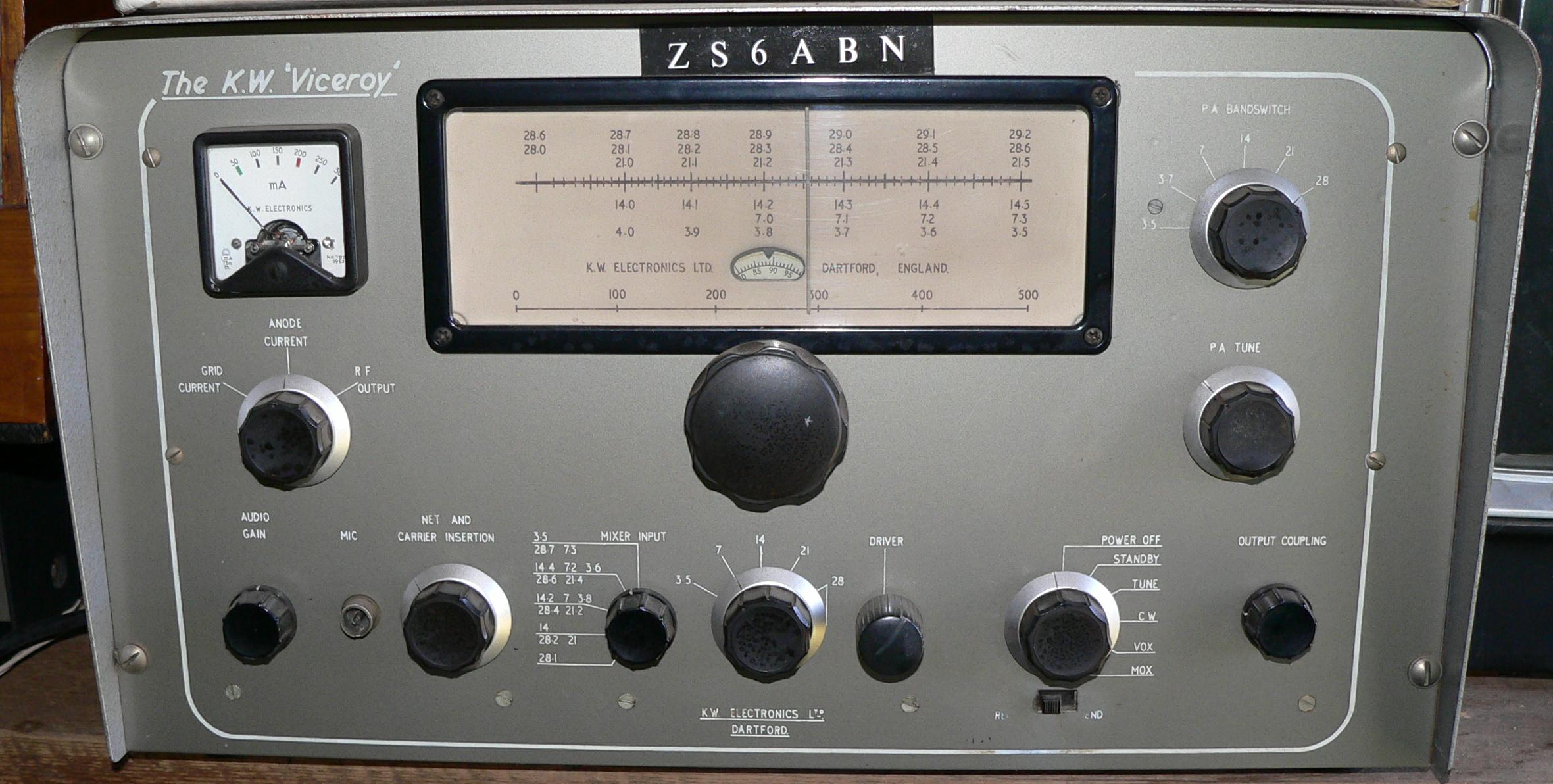
This transmitter is in excellent nick. It used to belong to ZS6ABN, but I bought it from a ham in Somerset West (and I can't remember who it was...)
There are four versions of the Viceroy transmitter.
Mark I: The crystal oscillator has four crystals, which gives five bands (80m doesn't need a crystal). The VFO covers a full MHz, and the crystal frequencies cause the bands to be in different places on the dial -- 15, 20 and 80m are on the left half of the dial and 40m is on the right hand side. There is no function switch (Tune/CW/Vox/Mox). The external PSU is roughly the same size as the Viceroy itself.
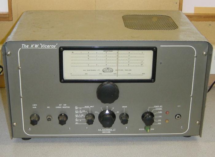
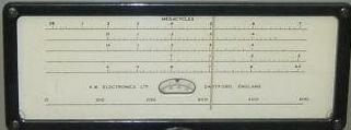
Look for the pillar case, the three knobs in a row on the lower left-hand side (carrier balance, audio gain, net & carrier insertion) and 28.0 to 29.0 MHz markings on the frequency dial.
Mark II: Still four crystals, but the 40m crystal is now 4.965 MHz which causes 7.0 MHz to coincide with 14.2 and 3.8 MHz on the dial. The function switch is located on the external PSU, which is about half the size of the Viceroy itself.
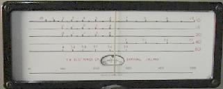
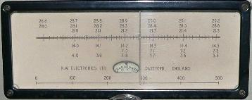
Look for the three knobs in a row on the lower left-hand side, and 28.0 to 28.7 MHz range on the dial.
I think that on late-model Mark IIs the anti-trip control was moved to the rear panel and the net control was combined with the carrier insertion control.
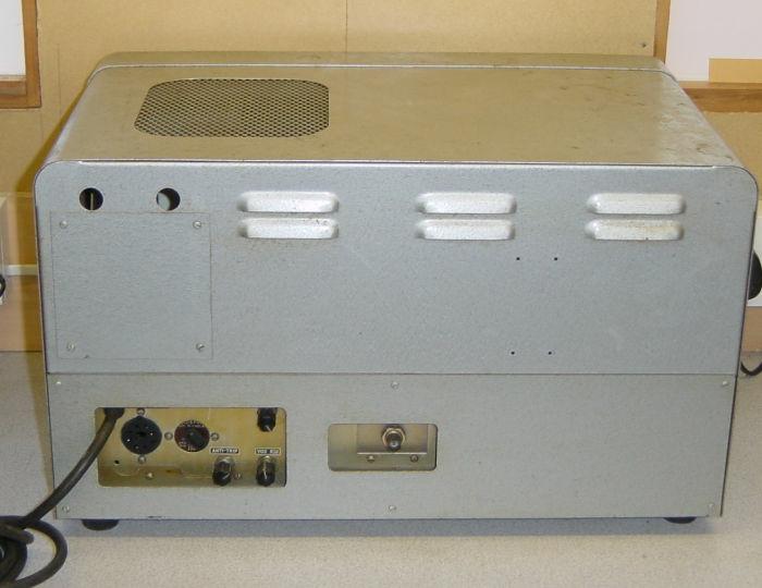
Mark III: The PSU is now internal, the function switch is on the front panel, and quite a few of the Mark II controls have been dropped or moved to the rear panel.
Look for the microphone jack on the lower left-hand side between the audio gain and net and carrier insertion controls).
Mark IV: Very similar to the Mark III, but with an antenna change-over relay.
Like a puppy, you need to turn this one over and look at the back end for the antenna change-over relay.
Later Viceroys were blue, but I don't know if this coincided with the change from Mark III to Mark IV.
|
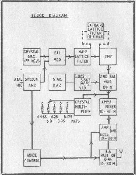
The Viceroy uses two mixers. The carrier oscillator at 435 kHz is modulated and filtered using
a crystal filter. There are three crystals in the Mark I filter and five in the Mark III, 432.6
and 434.15 in series with the signal and 435 as a shunt. This selects the lower sideband.
This signal is mixed with the VFO signal, filtered again, second mixed with a carrier from the crystal oscillator (except for 80m, where the crystal oscillator is inactive), and then ampified by the driver and the final amplifier. For 20, 15 and 10m the crystal oscillator frequencies are chosen so that the signal is subtracted, effectively inverting the sideband to USB (except for the Mark I, where 40m is USB too -- confirmed by this thread on Yahoo groups). The Mark I VFO covers a full Megahertz (3765 - 2765 kHz left-to-right), to cover as much of the 10m band as possible. As a result the other bands are scrunched together on the dial. Of course frequencies outside the band is possible, the frequencies below are the ones marked on the dial.
80m  :              [3565-3065] + 435 =  4000 - 3500  (LSB) (dial is marked back-to-front)
40m  : (5250 * 2) - [3065-2765] - 435 =  7000 - 7300  (USB)
20m  : (6000 * 3) - [3565-3165] - 435 = 14000 - 14400 (USB)
15m  : (6250 * 4) - [3565-3165] - 435 = 21000 - 21400 (USB)
10m  : (8050 * 4) - [3765-2765] - 435 = 28000 - 29000 (USB)
Mark II: VFO 3765-3065 In the absence of other information, I'm going to go out on a limb and say that the Mark II 40m coverage is 7.0-7.3 MHz. Yes, this spec sheet says 7.0-7.4 MHz, but the images of dials I have go to 7.3 and the maths matches this too.
80m  :              [3565-3065] + 435 =  4185 - 3495  (LSB)
40m  : (4965 * 2) - [3365-3065] + 435 =  7000 - 7300  (LSB)
20m  : (6000 * 3) - [3565-3165] - 435 = 14000 - 14500 (USB)
15m  : (6250 * 4) - [3565-3165] - 435 = 21000 - 21500 (USB)
10m  : (8050 * 4) - [3765-3065] - 435 = 28000 - 28700 (USB)
Mark III, IV: VFO 3665-3065
80m : [3565-3065] + 435 = 4000 - 3500 (LSB) 40m : (4965 * 2) - [3365-3065] + 435 = 7000 - 7300 (LSB) 20m : (6000 * 3) - [3565-3065] - 435 = 14000 - 14500 (USB) 15m : (6250 * 4) - [3565-3065] - 435 = 21000 - 21500 (USB) 10m A: (8025 * 4) - [3665-3065] - 435 = 28000 - 28600 (USB) 10m B: (8175 * 4) - [3665-3065] - 435 = 28600 - 29200 (USB) |
| Mark I | Mark II | Mark III & IV | |||
|---|---|---|---|---|---|
| Audio (mic) amp & cathode follower | 12AX7 | V5 | 12AX7 | 12AX7 | V1 |
| 435 kcs. amp | EF89 | V4 | EF89 | EF89 | V2 |
| 1st Mixer | 12AU7 | V2 | 12AU7 | 12AT7 | V3 |
| 2nd Mixer | 6CL6 | V6 | 6CL6 | EF80 | V4 |
| Driver | 6CL6 | V10 | 6CL6 | 6CL6 | V5 |
| Final (x2) | 6146 | V12, V13 | 6146 | 6146 | V6,V7 |
| Carrier Oscillator | 12AU7 | V1 | 12AU7 | 12AU7 | V8 |
| VFO | 12AT7 | V14 | 12AT7 | 12AT7 | V9 |
| VFO Amp | EF80 | V15 | EF80 (6BX6) | EF80 | V10 |
| VFO regulator | 0A2 | 0A2 | 0A2 | V11 | |
| Crystal Oscillator | 6870 | V11 | 6870 | EF80 | V12 |
| A.L.C. | 6AL5 | V16 | 6AL5 | 6AL5 | V13 |
| VOX Amp | 12AT7 | V7 | 12AU7 | 12AU7 | V14 |
| VOX Anti-trip | 6AL5 | V9 | 6AL5 | 6AL5 | V16 |
| Relay and Anti-trip Amp | 12AU7 | V8 | 12AU7 | 12AU7 | V17 |
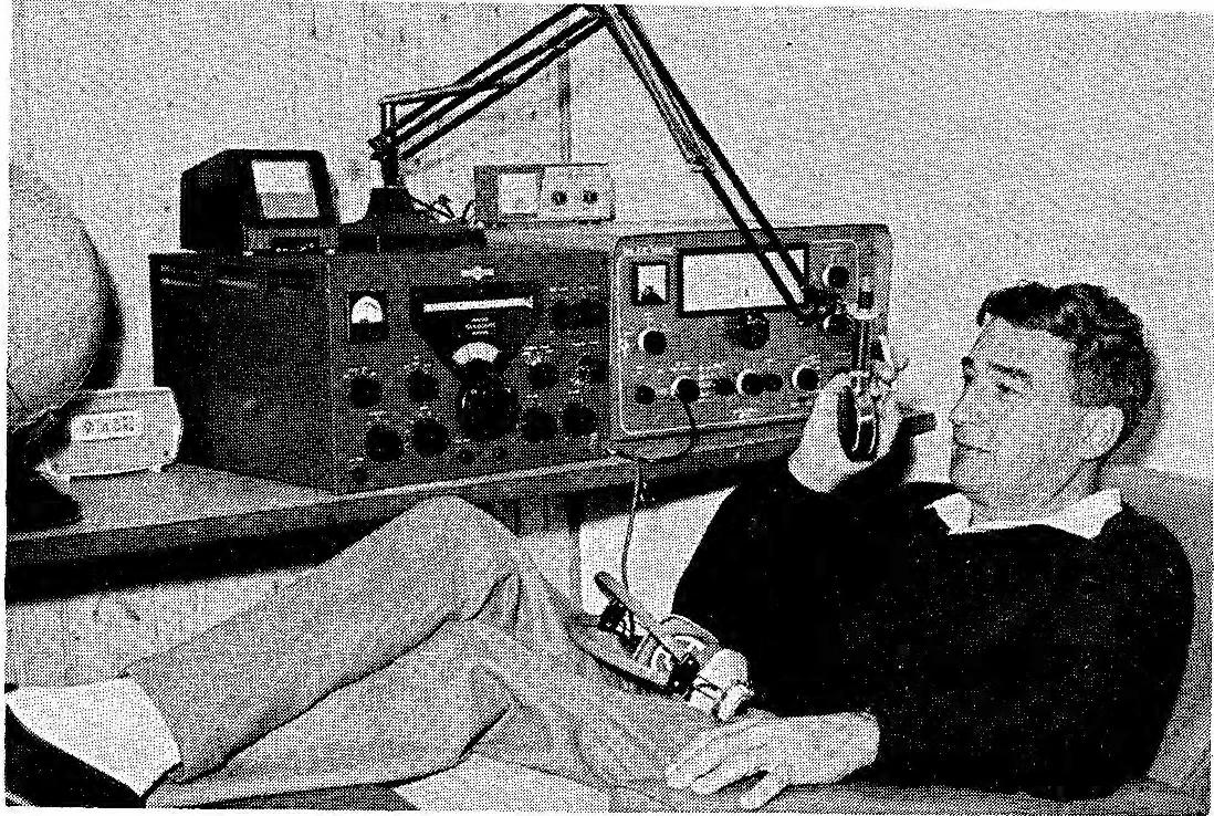
This picture of OM Harold Tronson ZS1CZ appeared in the September 1970 Radio ZS with the note that OM Harold went SK on the 19th of August. Note the Mark III next to the Collins 75A-4.
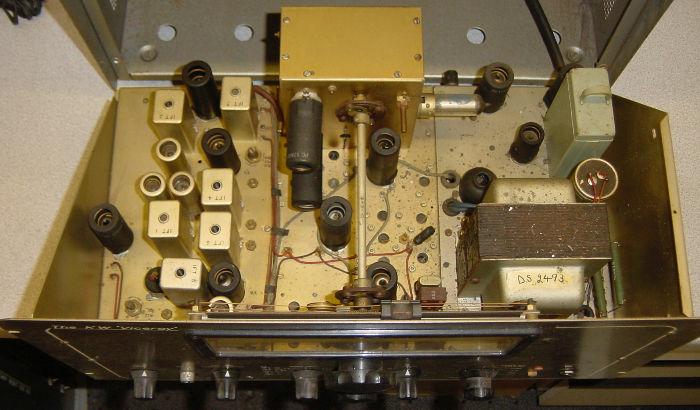
Here are some pictures of a Viceroy prototype sent to me by Roger Basford G3VKM.
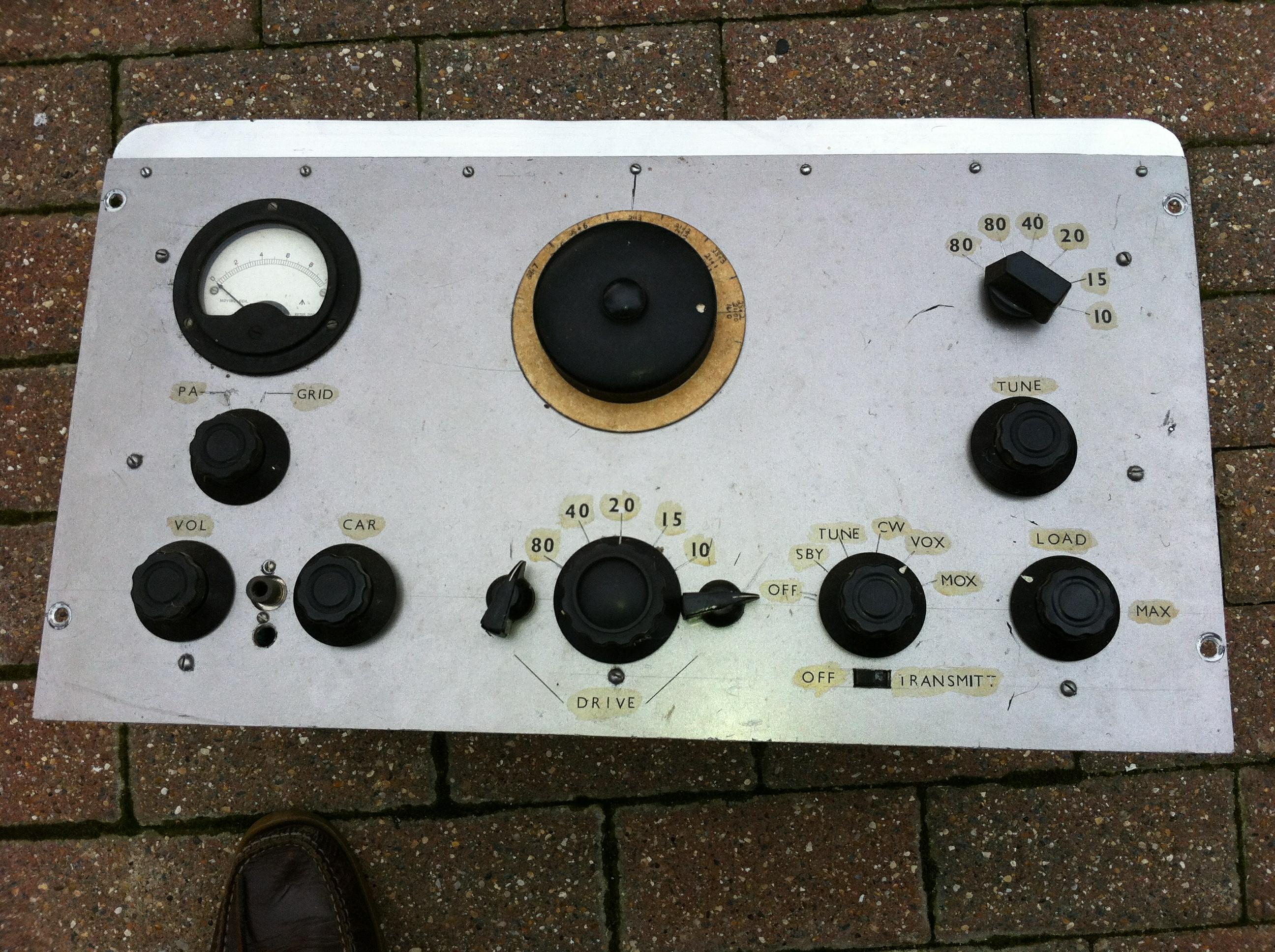
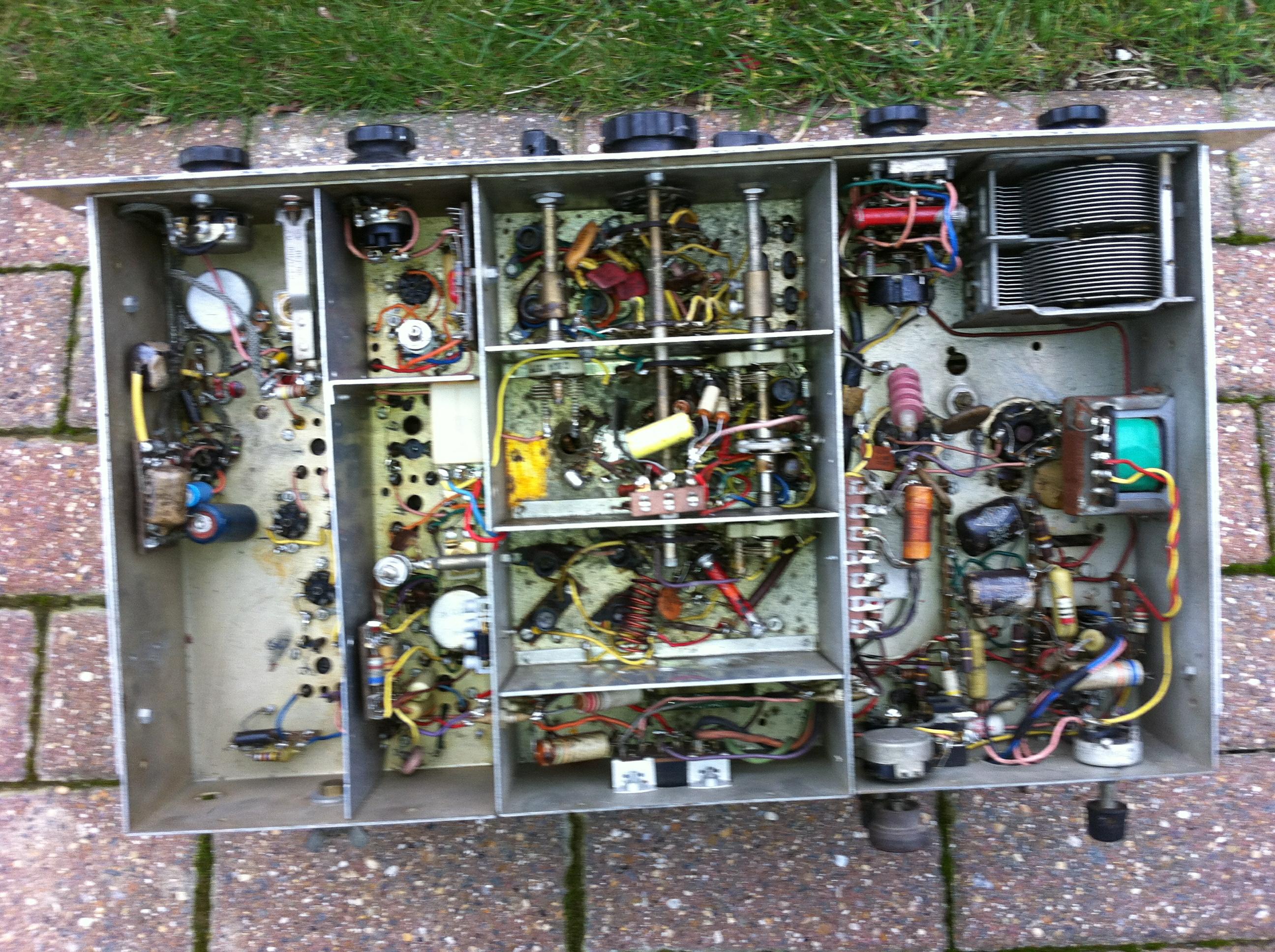
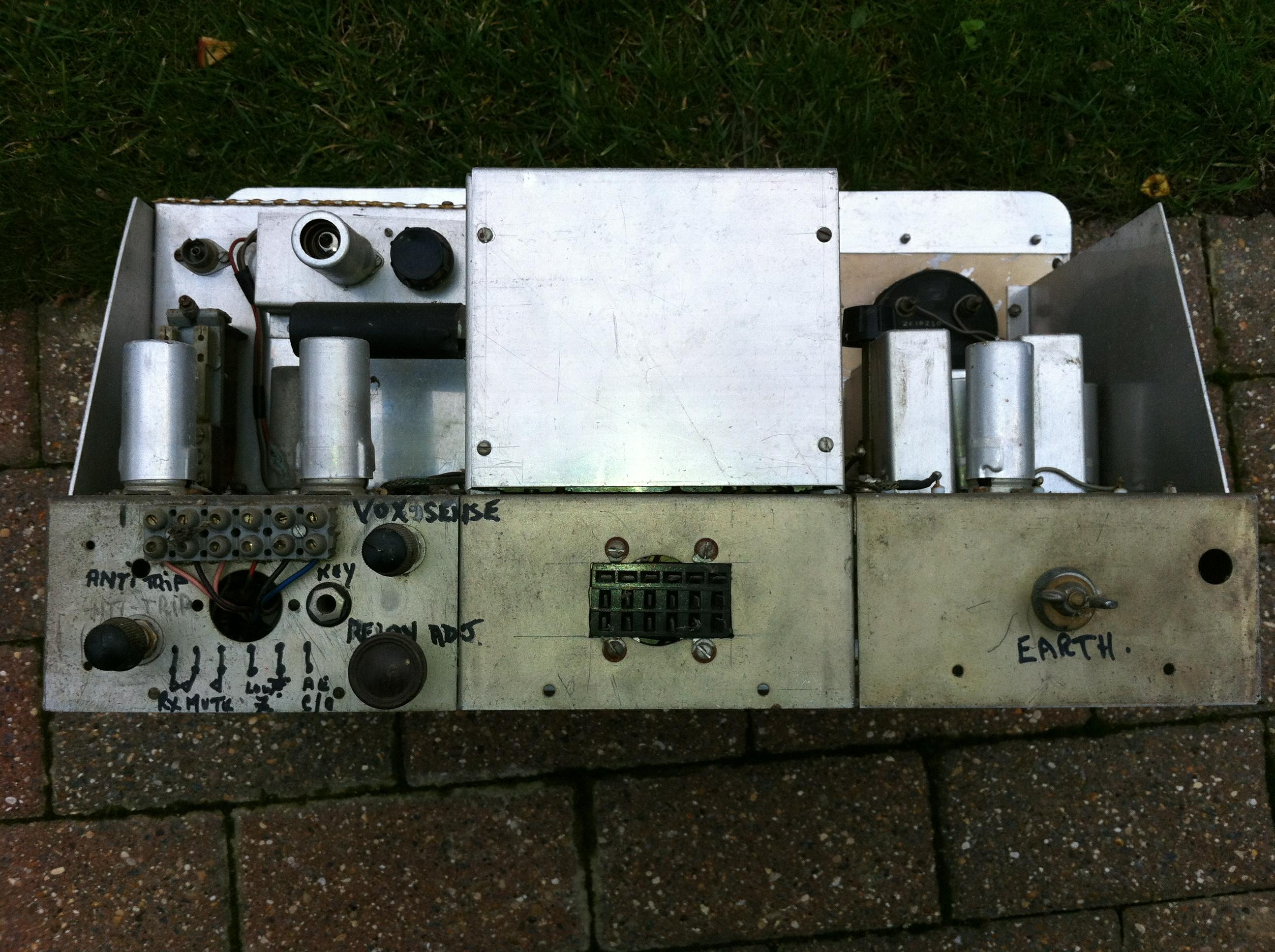
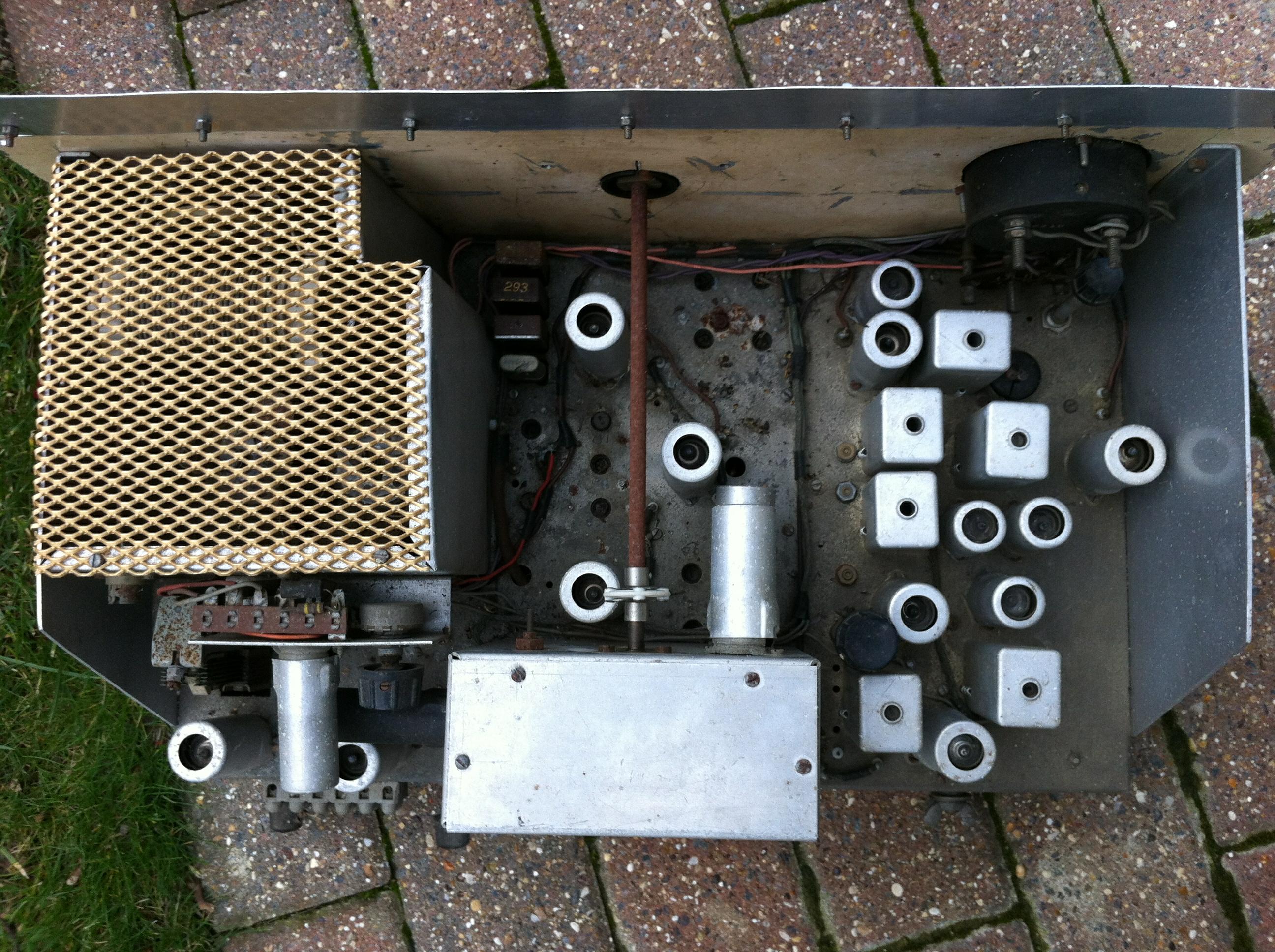
This is a K.W. Viceroy exciter (I'd call it a Mark II 1/2 -- looks like it only has five bands, and the dial calibration looks like Mark II, but it does have the microphone jack on the front panel).
|
|
Back to Wouter's Page | (This page last modified 2015-01-22) |