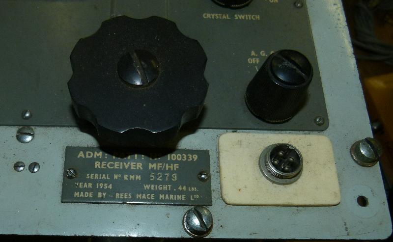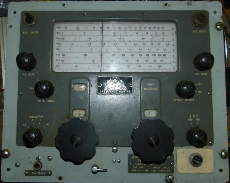

This is a Rees Marine "Receiver Outfit CAT" which is part of the Admiralty Type 619 transmitter / receiver system as fitted to smaller Royal Navy vessels in the fifties and early sixties. It's an extremely general coverage receiver, 60 kHz to 30 MHz.
|
Type 619 consists of an MF transmitter, an HF transmitter, the CAT receiver and
a Power Supply Unit. The transmitters are AM only (or CW of course), and the receiver
is fitted with a BFO for CW / SSB reception.
The unit was manufactured by Rees Mace Marine which later became PYE Marine. Keith has one bearing the PYE label while mine is Rees Mace Marine.
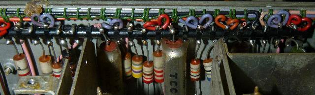
Production life: 1953 - 1965
Standard frequency range: MF TX 330-550 KHz, HF TX 1.5-16 MHz, RX 60kHz-30 MHz
Transmitter RF output: MF TX 15 Watts AM, HF TX 40 Watts AM
These sets are pretty badly documented on the web. Here's a video and here's the entry at radiomuseum.org. IMO These sets are very well built. Wires are neatly laced, and there seems to be a very strict colour coding system for all the wiring.
|
|
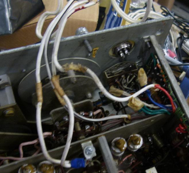
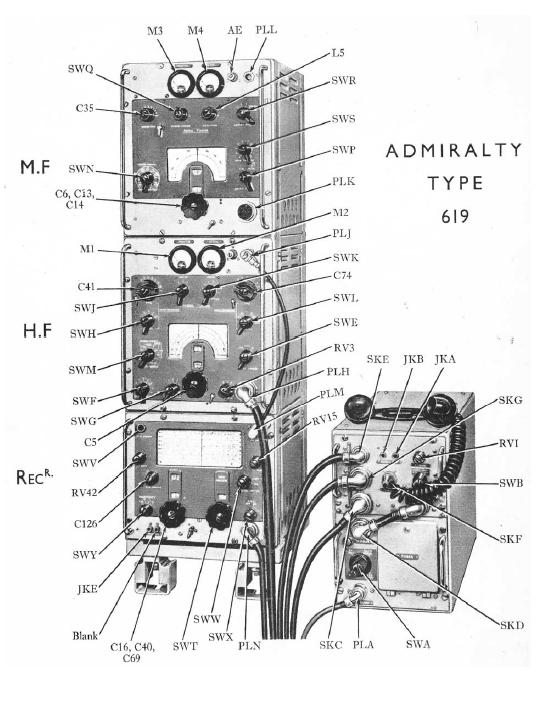
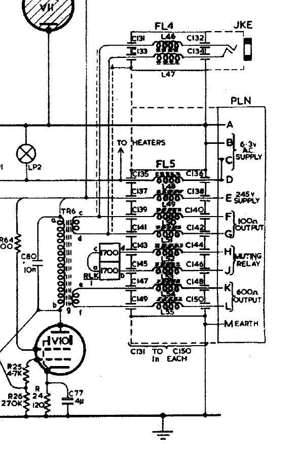
PLN is the missing connector. It carries 100 ohm and 600 ohm speaker output, a muting relay input, the 245V HT
supply and the 6.3V AC heater supply. The DPO removed the filter
FL5 along with it.
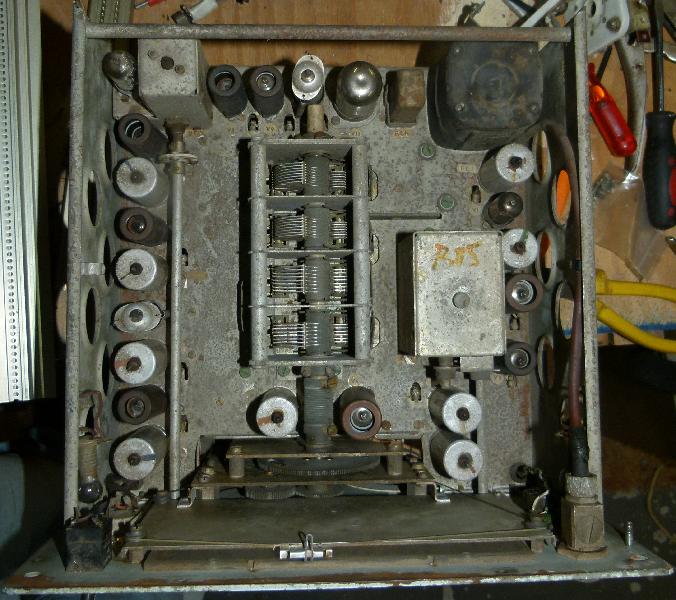
Tracing the wiring: The shielded cable from the headphone connector on the left-hand side of the front panel goes to the output transformer, connected to the same terminals are two blue wires. Blue = 100 ohm. Check. Next to this on the output transformer is a pair of green wires. Green = 600 ohm. Check.
Other terminals on the output transformer are two pink and one red. Seems a good idea to assume that the red is HT, tracing it a bit more shows that it goes to some 2.2k resistors, that checks out against the schematic.
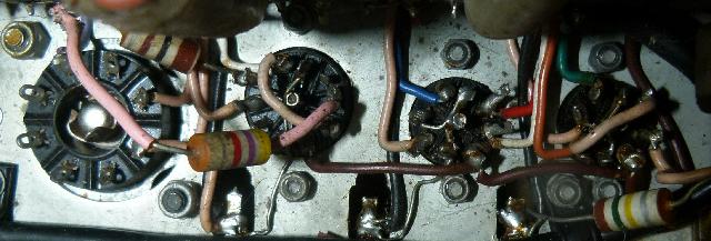
That leaves a brown wire and examination shows that every tube socket has a brown wire. Brown = heater, check. (That's V11 the voltage regulator, V10, V9 from left to right. You can't really see it in this reduced-size picture, but it checks out, one side of the heater to chassis and the other side to brown). TODO: buzz out red and brown to make doubly sure before applying power. I might be reckless but I'm not stupid. The two white wires are most likely the relay mute input, the relay has three white wires connected to it so that seems a safe assumption for now.
|
The Type 619 receiver covers 60kHz to 31 MHz in eight ranges.
| Range 1 | 60 - 125kHz | Single conversion, IF at 460kHz |
| Range 2 | 100 - 255kHz | Single conversion, IF at 460kHz |
| Range 3 | 255 - 675kHz | Double conversion, IFs at 1.4MHz and 460kHz |
| Range 4 | 675 - 1500kHz | Single conversion, IF at 460kHz |
| Range 5 | 1.5 - 3.4MHz | Single conversion, IF at 460kHz |
| Range 6 | 3.4 - 7.2MHz | Double conversion, IFs at 1.4MHz and 460kHz |
| Range 7 | 7 - 15MHz | Double conversion, IFs at 1.4MHz and 460kHz |
| Range 8 | 15 - 31MHz | Double conversion, IFs at 1.4MHz and 460kHz |
The higher ranges are double conversion (for selectivity) but of course Range 3 also has to convert up and then down to not step on its own dick. Selectivity is specified at 6kHz (wide), 4kHz (intermediate), 950kHz (narrow) and 700kHz (very narrow). It looks as if only the two wider settings are available when in double conversion?
| V1 | RF Amplifier | CV454 | Variable μ screened pentode | CV4009 6BA6 EF93 |
| V2 | 1st Mixer / Xtal osc. | CV2128 | Triode / Heptode frequency changer | 6AJ8 ECH81 |
| V3 | 1st Local osc. | CV133 | Triode amplifier / RF power valve | CV4058 6C4 EC90 |
| V4 | 2nd Mixer / 2nd Local osc. | CV2128 | Triode / Heptode frequency changer | 6AJ8 ECH81 |
| V5 | IF amp | CV131 or CV4015 | General purpose amplifying pentode | EF92 |
| V6 | IF amp | CV131 or CV4015 | General purpose amplifying pentode | EF92 |
| V7 | AGC diode / Det. diode | CV140 | Double signal diode | CV4025 6AL5 EB91 |
| V8 | Noise limiter | CV140 | Double signal diode | CV4025 6AL5 EB91 |
| V9 | AF amp | CV131 or CV4015 | General purpose amplifying pentode | EF92 |
| V10 | AF output | CV2127 | Video output pentode | CV4055 6CH6 EL821 |
| V11 | Stab. HT supply | CV395 | 150V voltage stabiliser, 5-45 mA | |
| V12 | BFO | CV131 or CV4015 | General purpose amplifying pentode | EF92 |
|
|
Back | (This page last modified 2014-11-11) |