Midland 70-066B

|
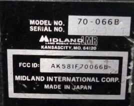
The Midland 70 series mobile transceivers were made from the early eighties
to the mid nineties. There are three types, Syntech I (ST-1), XTR and
Syntech II (ST-2). As far as I know they were made by Mitsubishi.
The 70-066B is a
Syntech I,
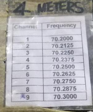
75 - 88 MHz, 40 Watt, 80 channel model. Mine is programmed for the
simplex FM channels.
Channel programming is via a 2716 EPROM, which needs to be removed and re-programmed to
change things. Of course one needs
a special programmer
(which I don't have).
|
|
Reverse Engineering the EPROM
Note: About halfway through this process
I learned that the
Midland LMR Yahoo group has an
executable that creates the EPROM image for you. You still have to desolder the EPROM to
program it in a conventional programmer, but that's trivial.
However, reverse engineering is still fun.
|
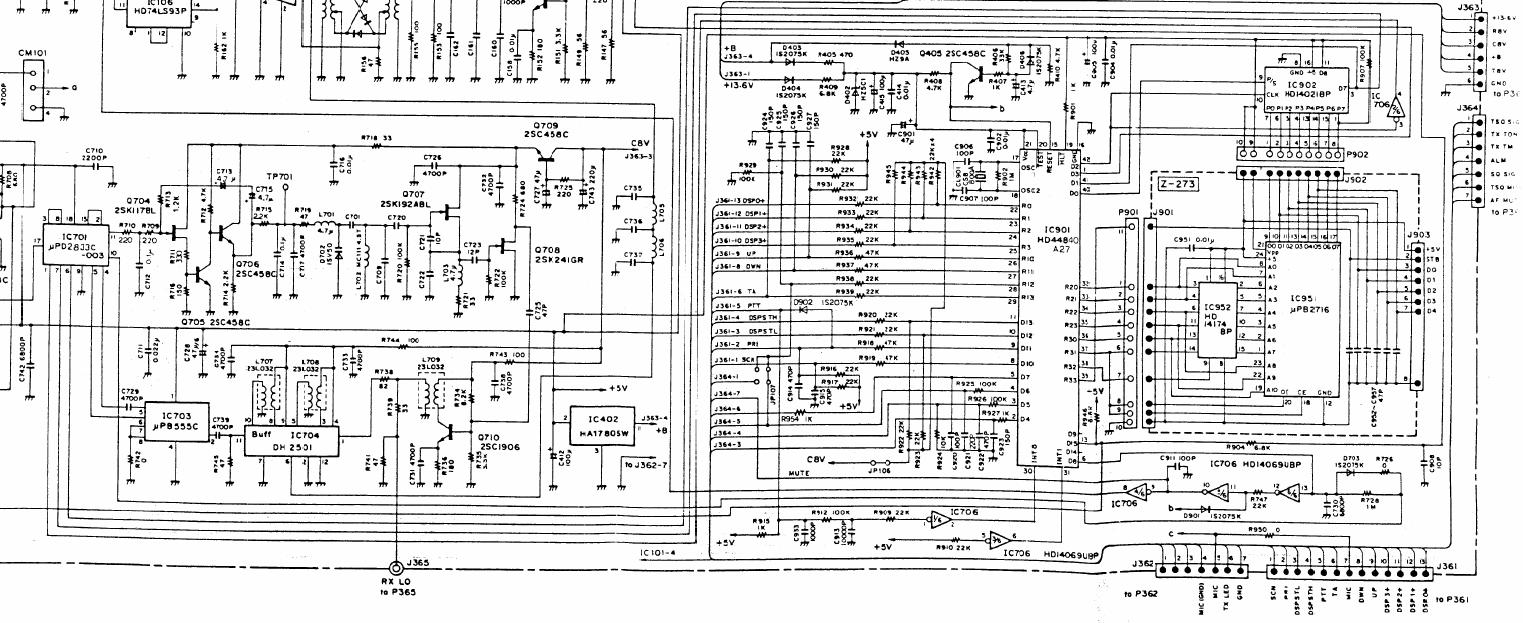
The PLL is IC701, labelled what looks like
uPD 2833C-003
in the schematic but MPD3805C-003
in the parts list. Programming is via pins 1, 7 and 6 (data, clock, load) which go all the
way across the page to the HD44840 microprocessor and the
4021 shift register.
The PLL works in conjunction with a dual-modulus prescaler, in this case a
uPB555C
which is
almost,
but not quite entirely unlike an LM555. Had me fooled for a while. Anyway, the uPB555C divides by
32/33 since M1 and M2 (pins 8 and 7) are connected to ground.
If you're not familiar with dual-modulus PLL, maybe the last page of the
MC145158 datasheet is a good place
to start.
NT = NP+A, where P = 32, A is the 7 bits going to the swallow counter and N
is the 10 bits going to the main counter.
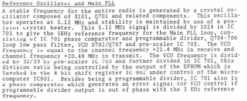
The 5.12 MHz clock is divided by 1024 to provide a 5 kHz reference. At a operating frequency
of say 70.2 MHz, the receive VCO frequency will be +21.4 = 91.6 MHz and the transmit VCO
frequency will be +20.48 = 90.68 MHz. This gives NT = 18320 and 18132 respectively.
|
18320 / 32 = 572.5 = %10 0011 1100 (10 bits)
18320 - (572 * 32) = 16 = %001 0000 (7 bits)

Alternatively

18320 = %100 0111 1001 0000 (15 bits) and then you have to extend the 5 low-end bits to seven
                            (this is what the datasheet is trying to tell you)
         100 0111 100 xx 1 0000 (17 bits)
         1000 1111 0000 1000 0 = 0x8F08 0
And since the datasheet says that the MSB of the 17 bit data word is shifted in first, and
since the MSB of the EPROM is shifted out first, I'd expect 8F 08 to occur somewhere in
the EPROM binary but it doesn't. The non-shifted
1 0001 1110 0001 0000 = 0x11E10
however does. Looks as if the processor starts shifting from byte zero for the channel,
reading the bit in via D1, and the first 15 bits get clocked through the PLL shift register
and fall out the other side, after 32 clocks the last 17 bits are in the PLL shift register
and then it gets loaded into the data register.
All the calculating was wearing me down, so I
wrote some code.
#  freq  Rx f  Tx f   divr  divt  Rx Data Tx Data
1 70200 91600 90680  18320 18136    11E10   11B18
2 70215 91615 90695  18323 18139    11E13   11B1B
3 70225 91625 90705  18325 18141    11E15   11B1D
4 70240 91640 90720  18328 18144    11E18   11B80
5 70250 91650 90730  18330 18146    11E1A   11B82
6 70265 91665 90745  18333 18149    11E1D   11B85
7 70275 91675 90755  18335 18151    11E1F   11B87
8 70290 91690 90770  18338 18154    11E82   11B8A
9 70300 91700 90780  18340 18156    11E84   11B8C
(I rounded up the 12.5 kHz channels after the fact)
These values all appear in my binary so I must be on to something.
00000000  FF FF FF FF FF 01 1E 10-FF 01 1E 13 FF 01 1E 15  ................  Receive channels
00000010  FF 41 1E 18 FF 01 1E 1A-FF 41 1E 1D FF 01 1E 1F  .A.......A......
00000020  FF 41 1E 82 FF 41 1E 84-FF FF FF FF FF FF FF FF  .A...A..........

00000200  FF FF FF FF 00 01 1E 10-00 01 1E 13 00 01 1E 15  ................  Receive channels
00000210  00 41 1E 18 00 01 1E 1A-00 41 1E 1D 00 01 1E 1F  .A.......A......  00 instead of FF
00000220  00 41 1E 82 00 41 1E 84-FF FF FF FF FF FF FF FF  .A...A..........  high byte

000003F0  32 FF FF FF FF FF FF FF-FF FF FF FF FF FF FF FF  2...............

00000400  00 FF FF FF 72 41 1B 18-09 41 1B 1B 56 41 1B 1D  ....rA...A..VA..  Transmit channels
00000410  41 01 1B 80 FF 41 1B 82-FF 01 1B 85 FF 41 1B 87  A....A.......A..  Some high bits set
00000420  FF 01 1B 8A FF 01 1B 8C-FF FF FF FF FF FF FF FF  ................  "41"

00000600  FF FF FF FF 00 41 1B 18-00 41 1B 1B 00 41 1B 1D  .....A...A...A..  Transmit channels
00000610  00 01 1B 80 00 41 1B 82-00 01 1B 85 00 41 1B 87  .....A.......A..  Some high bits set
00000620  00 01 1B 8A 00 01 1B 8C-FF FF FF FF FF FF FF FF  ................
But as I said, this is just for interest, get the MPR70 executable from the
Midland LMR Yahoo group
(run it in DOSBox).
12.5 kHz / 2.5 kHz channel spacing
In South Africa we started off with 25 kHz channel spacing with the option of moving to
12.5 kHz channel spacing when the bands get congested. The 70 MHz band is shared with other
users who tend to use 25 kHz spacing, which means that we can use the "in-between"
channels without interfering with one another. This is evidenced by the channels programmed
into my radio, except that the radio physically only offers 5 kHz spacing so the channels
of interest are all off by 2.5 kHz.
Converting the 70-066 to "splinter" frequencies
Midland calls them "splinter" frequencies. It doesn't really matter whether the
channel spacing is 12.5 kHz or 2.5 kHz, either will give me what I need.
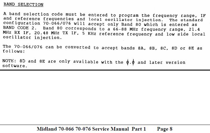
The Service Manual is wrong.
The manual for the 70-1000 programmer corrects this. 80, 8B and 8D
are high side injection, 8A, 8C and 8E are low side injection.
I fired up the software and created an EPROM image with the first channel at 70.200 MHz receive and
transmit. Did this for all six codes, and dumped the EPROM images.
code Rx bin Tx Bin Rx div Tx div  Ref  Rx VCO  Tx mix   Rx injection                             Tx

 80  011E10 011B18  18320  18136   5   91.600  90.680 : 91.600 - 70.200 = 21.400 (high side inj) 90.680 - 20.48 = 70.200
 8A  009880 009B18   9760   9944   5   48.800  49.720 : 70.200 - 48.800 = 21.400 (low side inj)  49.720 + 20.48 = 70.200
 8B  007280 006F90   7328   7152  12.5 91.600  89.400 : Same as 80                               89.400 - 19.20 = 70.200
 8C  003D00 003F90   3904   4080  12.5 48.800  51.000 : Same as 8A                               51.000 + 19.20 = 70.200
 8D  011E20 011B30  36640  36272   2.5 91.600  90.680 : Same as 80, uses 64/65 swallow counter   90.680 - 20.48 = 70.200
 8E  013100 013690  19520  19888   2.5 48.800  49.720 : Same as 8A                               49.720 + 20.48 = 70.200
Note that the 8D Rx value is 0x11E20 = %0001000111100 01 00000. The "filler" bits are not zero, which
tells me the swallow counter value is not five bits but six, i.e. the dual modulus prescaler is a 64/65 counter
and not a 32/33 counter. Some googling tells me the uPB571C (pin compatible to the uPB555C) will do the job.
Since my goal is to get the splinter frequencies, I can ignore the low side injection option, leaving me with the choice
of 8B (which implies changing the transmit VCO frequency to 19.2 MHz) and 8D (which uses a different swallow counter).
Since the uPB571C is
easily found on eBay, 8D would be my preferred route.
8D is also easier because with the transmit VCO not changing, only one reference frequency needs to change.
80/8A: 5.12 MHz / 1024 =  5   kHz PLL reference, 5.12 MHz / 4 = 1.28 MHz = [Tx mix - Tx VCO | Tx VCO - Tx mix] / 16
8B/8C: ?               = 12.5 kHz PLL reference, ?            = 1.2  MHz = [Tx mix - Tx VCO | Tx VCO - Tx mix] / 16
8D/8E: 5.12 MHz / 2048 =  2.5 kHz PLL reference, 5.12 MHz / 4 = 1.28 MHz = [Tx mix - Tx VCO | Tx VCO - Tx mix] / 16
The 5 kHz reference needs to be divided by two to give a 2.5 kHz reference for the PLL. It looks as if the spare flip-flop in
IC702 (74LS93) might do the job, but I am worried about the control line from the processor D15 to IC702 pins 2 and 3. The
divider might be disabled during receive.
Update: I got hold of the 70-2138 (2.5 kHz steps, low side injection) and 70-2139 (2.5 kHz steps, high side injection)
instructions. The hardware required consists of 150mm 28AWG wire (70-2138) and 150mm jumper wire + a uPB571C prescaler (70-2139).
This confirms that my analysis is correct. Go me. The instructions also call for grounding ping 2 and 3 of IC701 and cutting the
trace to the micro, so my guess that the divider is only enabled during transmit is correct, but obviously running it all the
time doesn't make a difference.
70-2138 Page 1
70-2138 Page 2
70-2139 Page 1
70-2139 Page 2
70-2139 Page 3
Of course, for true 12.5 kHz channel spacing I'd also need to install 70-2135, which consists of a replacement 21.4 MHz crystal
filter and two replacement 455 kHz ceramic filters. But I'm not really worried about that, as I said we use the "12.5 kHz"
channels mostly and there's no real traffic on the "25 kHz" channels.
Still no idea how modes 8B/8C work.


