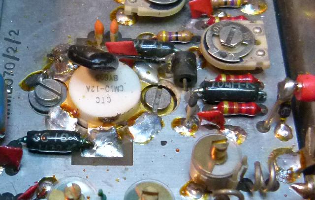
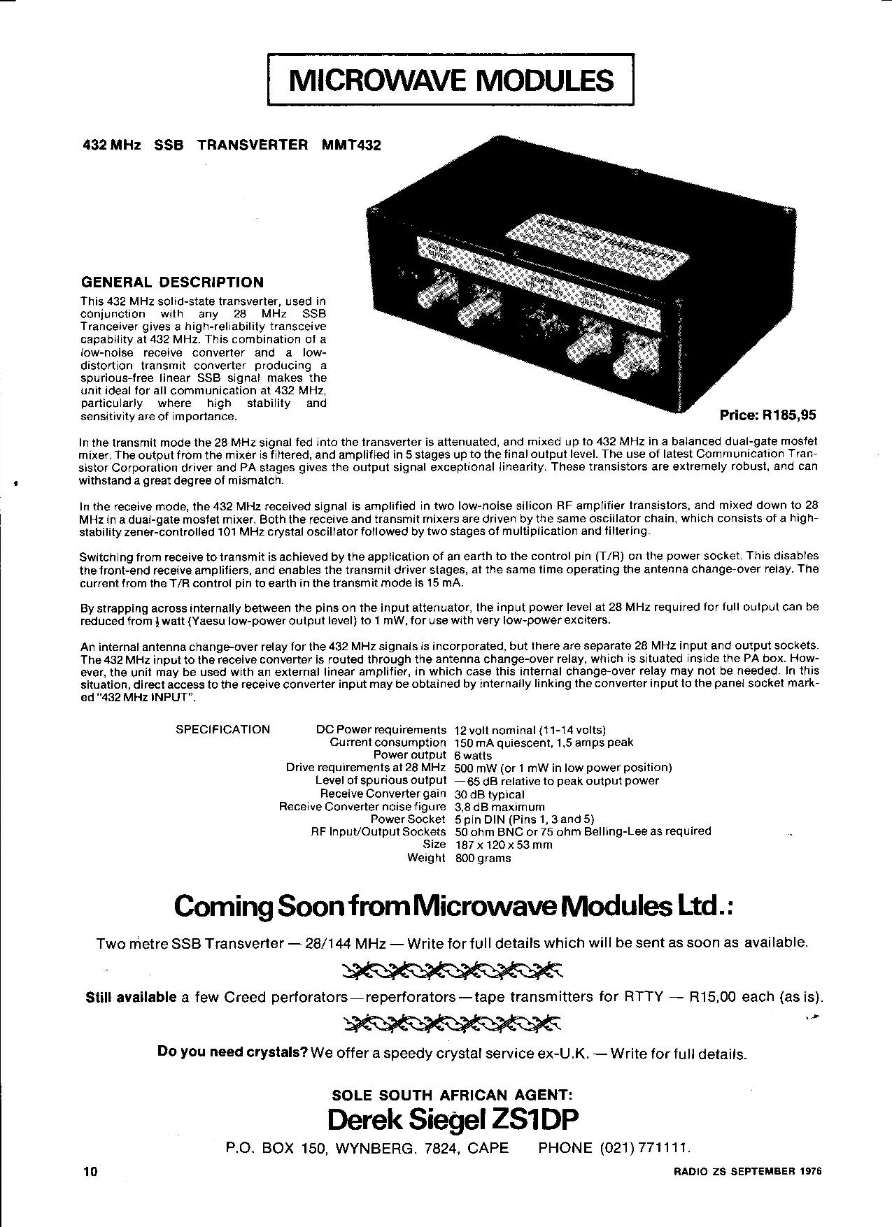
Output transistor is a CM10-12A which crosses to the MRF641, good for about 15W -- but this advert from Radio ZS September 1975 only claims 6W.
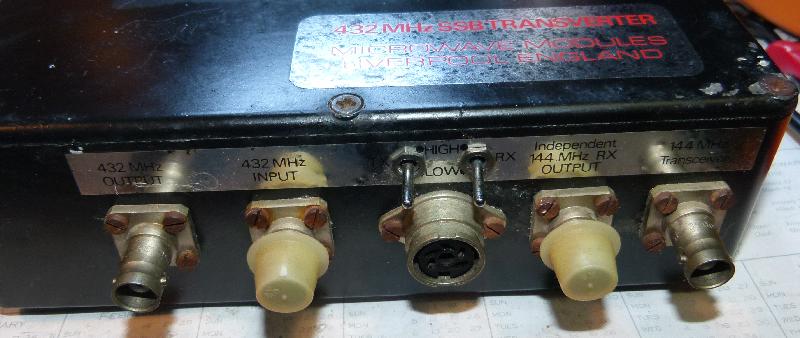
There's quite a bit of up- and down-converting happening here. Firstly, the 70cm band is 4 MHz wide, compared to the 2 MHz wide 2m band (in the UK, where these transverters were made). Therefore, coverage is in two separate blocks. So, the main oscillator runs at either 100.5 or 101 MHz. This is doubled twice to get 402 or 404 MHz.
Meanwhile, there's also a 114 MHz oscillator. Combined with 144-146 MHz, this gives a 30-32 MHz signal which in turn is combined with the 402 or 404 MHz signal to give 432-434 and 434-436 MHz. I'm guessing there's a good reason why they did it like this.
The Wirral & District Amateur Radio Club has the manual for download.
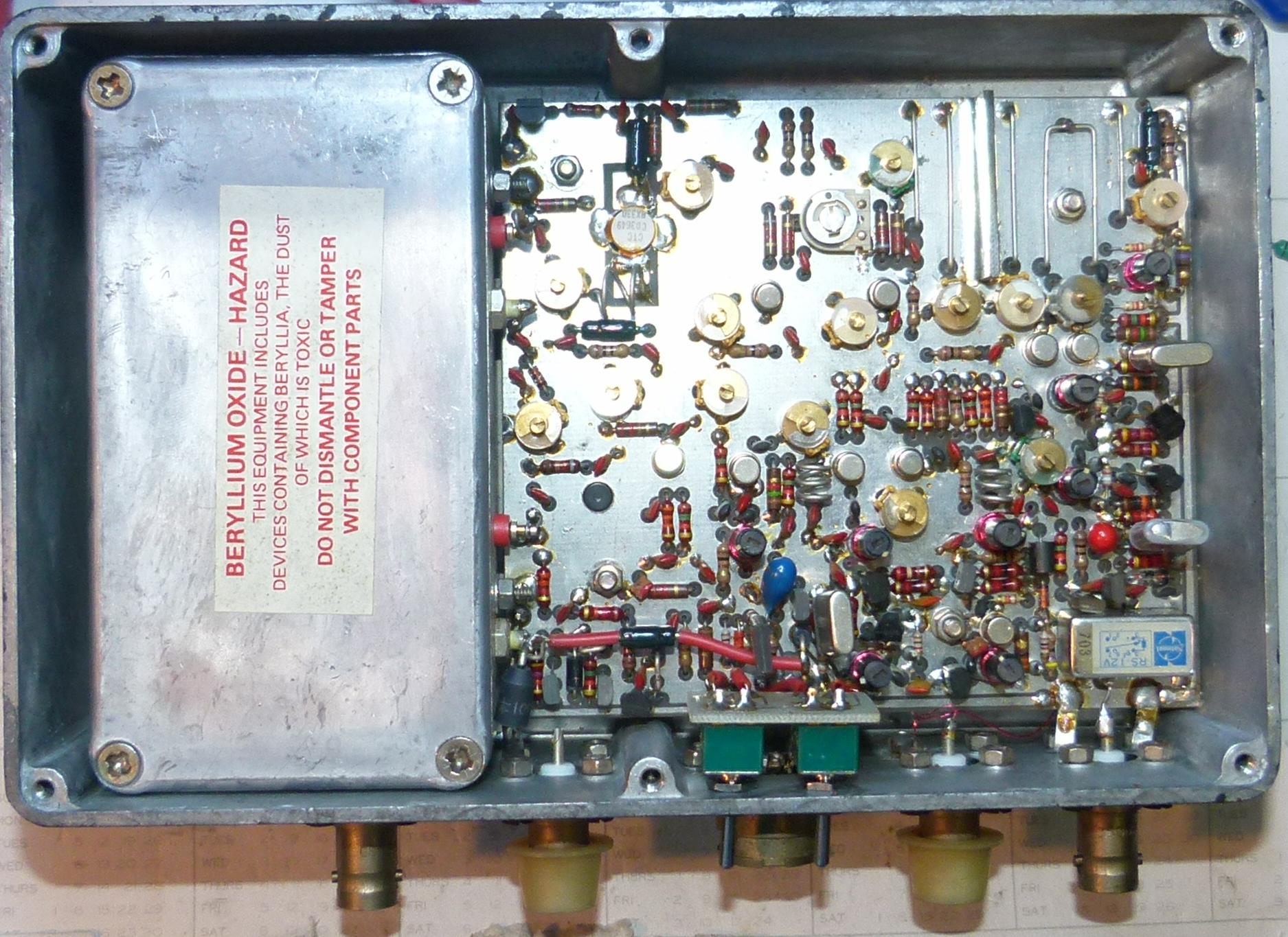
Here are some photographs and the schematic for the MMT432/50 transverter which has a 50MHz IF.
|
|
Back | (This page last modified 2025-03-02) |