To fix the set properly, I had to reverse engineer the wiring on the circuit board and on the chassis, and the connections between the two. To do this I assigned net names, like one would do with modern PCB layout.
| Net name | Components | Off board connections | Chassis connections |
|---|---|---|---|
| NET01 | R3A C5A | P2A2 (red wire) | |
| NET02 | C5A R9A R10A R2A | V1A1 (bare to R2A/R9A), V1D7 (yellow to R10A) | |
| NET03 | R9A C8A | V1A7 (yellow) | V2A1/V2A5, VC4A rotor, VC2A/VC3A frame, Reduction Drive frame |
| NET04 | C8A R5A R4A | R1A (green wire) | |
| NET05 | C6A C5C C5B | V1B1 (yellow to C6A), V2A7 (yellow to C5B) | |
| NET06 | C5C R5A R5B | L1BS (blue) | |
| NET07 "Black" | C6A R4A VR1A2 C6B R11A C9A R7A C6D C6E C6C | V1C1/V1C5 (bare to C6B) | P1A3, C8B |
| NET08 | R5B VR1A3 | ||
| NET09 "Yellow" | VR1A1 VR1B2 | P1A1 (yellow to VR1A1) | V1B7 |
| NET10 | C5B VR1B1 R3B | V1B3 V2A3 (blue wire from V1B3 to circuit board to V2A3) | |
| NET11 | R4B R11A R10A C5D C6E | V1D1 (yellow to C5D) | V1C7 (yellow) |
| NET12 | C9A C7A R6A | V1C2 (yellow to C9A) | |
| NET13 | R4B | V1C6 (bare) | C2A |
| NET14 | C7A R7A R1B | ||
| NET15 | R1B | V1D6 (green to R1B) | |
| NET16 | C6D R6A R12A | ||
| NET17 | R8A C5D | V1D3 (blue wire) | |
| NET18 "Red" | R3A R3B R12A R8A C6C | L1AS (red), T1A3 (red to C6C) | Red T1A3 to P1A4 to L2A1 |
| NET19 | R2A C2B | V1A6 (green to R2A) | green to V2A4/C2B |
| NET20 | VR1B3 R2B | ||
| NET21 | R2B C6B | Blue to L2BS |
In addition to that, there are a number of components wired together on the chassis but not connected to the circuit board.
| 1 | Antenna connector to L2AS / C3A |
| 2 | L2AF/C3A to P2A2/C2E |
| 3 | C2E to P2A5 |
| 4 | P2A1 to C2B to (green wire) C3A stator / VC1A (padder mounted on VC1A) |
| 5 | P2A3 to chassis (next to VC4A / C8B) |
| 6 | P2A4 to V1A2, V1A3 (yellow wire through V1A socket mounting hole) |
| 7 | P2A6 to C1A |
| 8 | C1A to R1A to V2A6 (green wire) |
| 9 | V1B2 to L2A (yellow wire) |
| 10 | V1B6 to L1BF |
| 11 | V1C1 to tie point ("black") to C8B |
| 12 | V1C3 to L2BF |
| 13 | V1D2 to T1A4 (yellow wire) |
| 14 | V2A2 to L1AF |
| 15 | L2A to "red" |
| 16 | T1A3 to "red" |
| 17 | T1A1 / T1A2 to 5 way panel |

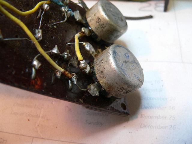
The pots are a bit unusual. Most modern pots have the centre pin as the moving contact, but in this case the case (pin furthest away in this photograph) is the slider. The centre pin is 1. So looking from the back, the numbering is 3 1 2 left to right. Something to watch out for.
|
|
Back | (This page last modified 2014-01-22) |