My IC-703 came with one working output transistor. Good enough to sell the rig as "working" but not much more. I tried replacing the RD07MVS1 but they are a bitch to replace.
Granted, by now the PCB had been reworked at least twice (the finals I got were not the original finals) so things were a bit iffy.
| C165 | 0.1 | C2012 JB 1C 104K-T | 2012 (0805) |
| R160 | 2k2 | ERJ3GEYJ 222 V (2.2k) | 0603 |
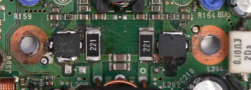
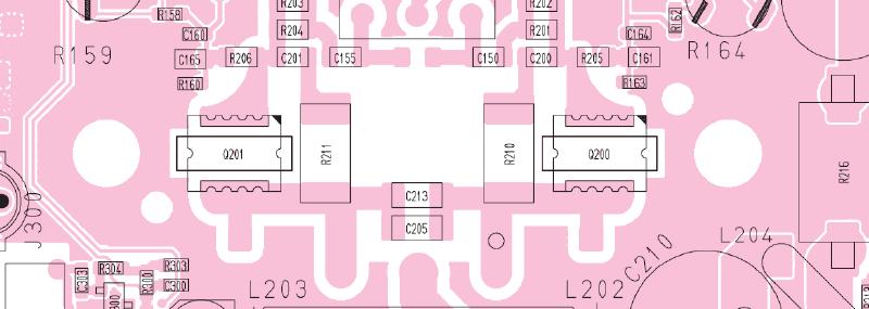
| R206 | 33 | MCR10EZHJ 33R (330) | 2012 (0805) |
| C201 | 0.1 | C2012 JB 1C 104K-T | 2012 (0805) |
| C155 | 0.1 | C2012 JB 1C 104K-T | 2012 (0805) |
| R211 | 220 | ERJ1TYJ 221U (220R) | (2512) |
| C213 | 39p | GRM31M2C2H390JV01L | (1206) |
| C205 | 39p | GRM31M2C2H390JV01L | (1206) |
| R210 | 220 | ERJ1TYJ 221U (220R) | (2512) |
| C150 | 0.1 | C2012 JB 1C 104K-T | 2012 (0805) |
| C200 | 0.1 | C2012 JB 1C 104K-T | 2012 (0805) |
| R205 | 33 | MCR10EZHJ 33R (330) | 2012 (0805) |
| R163 | 2k2 | ERJ3GEYJ 222 V (2.2k) | 0603 |
| C161 | 0.1 | C2012 JB 1C 104K-T | 2012 (0805) |
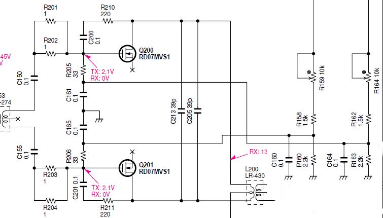
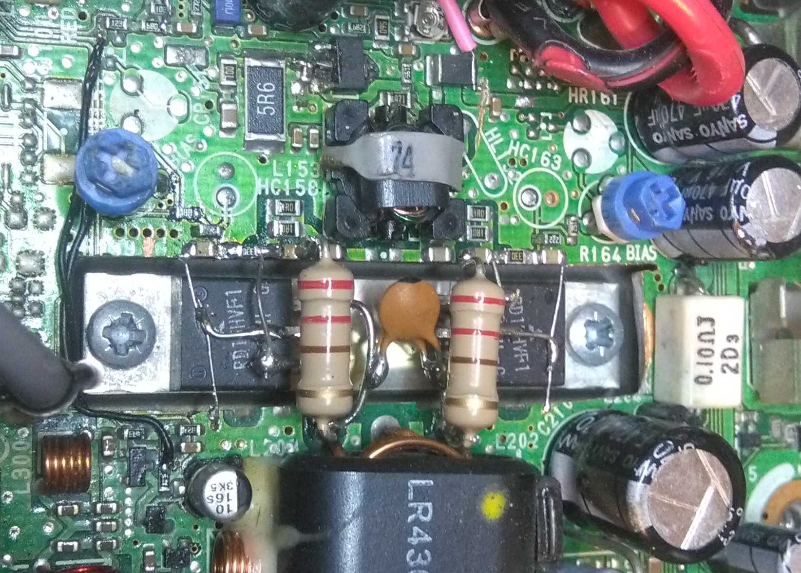
Then in a fit of not double-checking I assumed (never assume) that the current to the finals goes through the fuse right there next to them on the board, so that's where I inserted the multimeter to set the idle current. Don't do that. RD07MVS1s can and do catch fire.
So much for that then. Something had to be done.
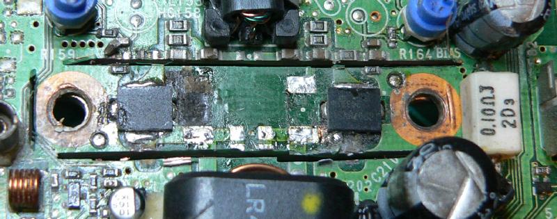
I should have been a bit more conservative, I think. But I wouldn't have been able to save those two traces, so I'll just have to add wires. One trace runs from R300/R305 to R306, the other is the T8 line between R100 and R250/R301.
It's ugly, but I'm back on the air again. With cheaper, more robust finals. I'll call it a win.
|
|
Back | (This page last modified 2020-04-13) |