The FT-790RII is a mobile 70cm all-mode transceiver that can also run off internal batteries for portable use -- an electric handbag, so to speak.
|
|
Most vintage secondhand radios suffer from Dreaded Previous Owneritis to some extent. This one was no exception.
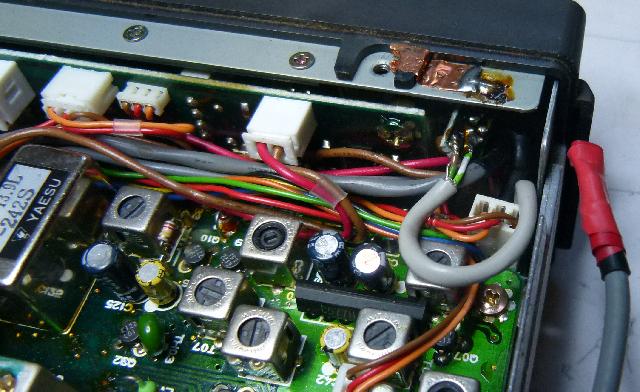
This is the top end of the volume control on J03 (i.e. the audio before being attenuated by the volume control) fed (through the lowpass filter) to the front panel antenna BNC. I suppose if you want to run a base station packet system this is not a bad way of getting the audio out. But I reversed the mod. |
|
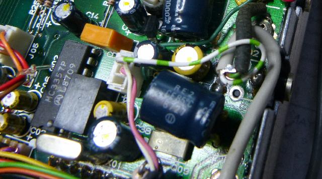
This mod is more interesting. It's right next to the "key" socket, so I assumed it's a key click filter or something.
Not so. As far as I can tell, it's a factory mod, it switches in more capacitance in the filter circuit on pin eight of the audio output amplifier in some mode (this is not one of my better researched analyses) -- maybe it improves QSK or something.
|
(I'm guessing here)
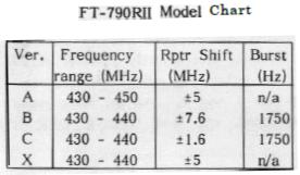
A - Region 2 USA, Region 3 Australia (430-450 MHz, 5 MHz repeater shift, no tone) |
|
The differences between the frequency range of the A, B, C, F and X models are determined by option diodes on the SW unit. The
FT-790RII schematic does not include the schematic for this board, but the
FT-690RII schematic does. There seems to be very little difference
between the 2m, 6m and 70cm radios, they all use the same F2822101 SW Unit (it's actually just the Main and PLL units that differ,
and even then the basic designs are the same).
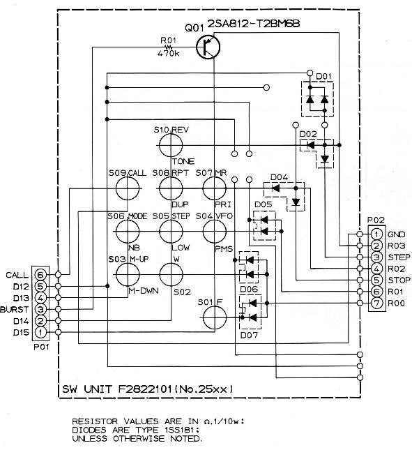
There are four rows and four columns, giving 16 switch / pushbutton positions. Of these, nine are pushbuttons, one is a transistor (more on that below), four are hard-coded, and two go off-board as STOP and STEP. The hard-coded inputs are D01, D03, R02 and R03 which form connections between D12 and R00, R01, R02 and R03. STOP and STEP go back to the processor board where they connect to D13 via a switch (STOP) and a jumper (STEP). So I took the thing apart and started playing (don't be a plonker and take the whole radio apart like I did -- you can just remove the front panel after removing the nuts holding the controls and the connectors). Presented here for the first time ever:
|
As far as I can see, the 290R2, 690R2 and 790R2 all use the same mask-programmed firmware, so that the CPU Unit doesn't know what model radio it's in -- the mode jumpers tell it how to program the PLL and what to display. Since the first two digits are not displayed, "4.000.0" might be 54.000.0, 144.000.0 or 434.000.0.
The PLL boards for the different models use different reference crystals -- the 790R2 A uses 184.175MHz while the others use 183.060, the 290R2 uses 122.0315 or 126.7215, while the 690R2 only has one model with a 54.9685MHz crystal. Using a jumper setting that doesn't match the crystal won't work.
What is obvious is that the jumpers don't act independently -- there isn't one jumper to select 430-450 instead of 430-440 and another jumper to select the repeater offset. This means I can't extend the range of my C model to include the 440-450MHz segment while keeping the 1.6MHz repeater offset.
|
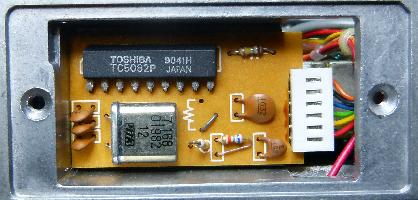
The FT-790RII can be fitted with either a tone burst board (1750 Hz, for European repeaters) or a
CTCSS (subtone) board. The B and C models
were factory fitted with the FTE-2 tone burst board, while the
CTCSS option is called the FTS-7. There's only space for one at a time.
If the tone burst board is fitted, the CALL button on the front panel activates it. If not, the CALL button recalls a special memory channel. This is the 1750 Hz board, based on the Toshiba TC5082 (7.168 MHz / 4096 = 1750 Hz). The FTS-7 uses an MN6520 encoder / decoder.
|
OK, but how does the radio know what to do?
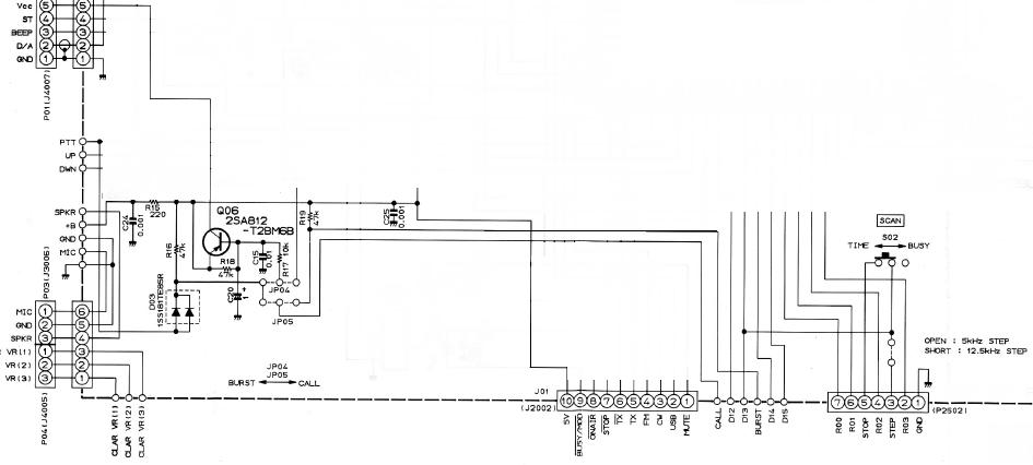
Let's start with the connections to the right of J01 at the bottom. The CALL button grounds the signal labelled CALL, which is connected to the centre pin of JP05. Let's assume both jumpers are to the left, i.e. "BURST" as indicated on the schematic.
The lefthand side of JP05 is connected to the two parallel diodes, so effectively the CALL button grounds the PTT line. The lefthand side of JP05 is also connected to the lefthand side of JP04, and with both jumpers on the left this means that the CALL button grounds the base of Q06 via R17, turning it on, and providing +5V from J01 to P01 pin 5 ("Vcc"). The block diagram shows that this is Vcc to the tone board.
So, pressing the CALL button supplies power to the tone board and enables transmit. This is standard toneburst.
With the jumpers to the right, the CALL button is fed back to the BURST connection, which turns Q01 on the SW unit on when the CALL button is pressed. Q01 is wired to the switch matrix, so CALL becomes just another key. When the user turns on CTCSS (F-TONE) the processor turns Q06 on via pin R22 (not shown on my somewhat redacted schematic above) providing power to the CTCSS board, if fitted.
With the jumpers in the "BURST" position, it enables toneburst. With the jumpers in the "CALL" position, the CALL memory channel is selected. The routing of the CALL signal via the BURST signal to select the CALL channel had me puzzled for a while, as did the "Vcc" signal which is only Vcc for whichever tone board is fitted.
But, A2 also goes to the MC145145 PLL chip. That's why there's an RC circuit on the base of Q06. The high-frequency programming pulses don't turn Q06 on, and of course CTCSS or toneburst is not an issue while reprogramming the PLL anyway.
I would also speculate that the processor doesn't actually know whether toneburst or CTCSS is fitted. One can most likely add a subtone board to the B and C models, you just need to add a transistor sort-of-parallel to Q06, driven from processor pin R22, and supplying power to your CTCSS board. And if you have a spare switch on the microphone or somewhere you can wire that back to BURST and get the memory function of the A models too. If this is the kinds of thing that floats your boat.
I need to add a CTCSS encoder.
When I bought the radio I knew that the M57745 RF Module in the FL-7025 linear amplifier was blown and had been bypassed. I found a replacement on eBay, from China.
Having seen reports of counterfeit electronics from China, I wanted to make sure the replacement was legit, so I opened it up to compare.

Looks legit. No, seriously. Looks like a somewhat later design, with printed inductors replacing the wire ones of the original, but the transistors are the same shape and size and everything follows the same basic design.
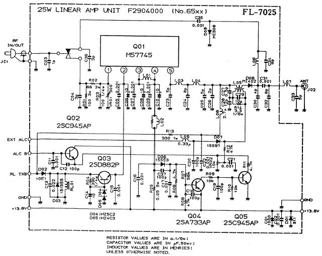
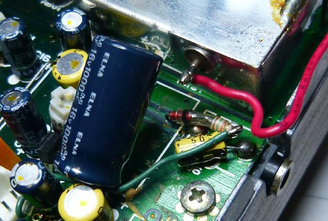
VR01 controls the amount of attenuation before the amplifier, and therefore will set the output power. The FT-790RII puts out 2.5W, and the attenuator drops that by 9.5dB to give about 280mW which should drive the M57745 to just under 40W, according to the datasheet.
VR02 sets the ALC but I have to figure out how that works.
There are various copies of the schematic floating around, but all of them are missing the PA part of the "PLL/PA Unit". I have not been able to find the schematic for the 70cm PA, only the 2m and 6m ones. (If you want to highlight parts of the schematic to understand things better, like I did, you can spend a lot of computer time to come up with the magic number "040159").
You will find a service manual for the FT-290RII on the net, but not for the FT-790RII. Or at least, I have been unable to find it.
|
|
Back | (This page last modified 2020-04-13) |