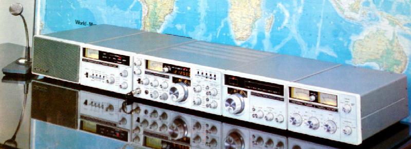
Yup, the whole lineup. In white. It was different. It was beautiful. I was seriously on the wrong side of the 10th Commandment.
1983. I was in high school. Hamrad was in Buitengracht street in Cape Town*.
They had this.
Yup, the whole lineup. In white. It was different. It was beautiful. I was seriously
on the wrong side of the 10th Commandment.
(The SARL website tells me that the price for the FT-107, new, was R789. That was a lot of money, back in 1983).
* And ERL, the Electronic Research Lab, was on the other end of town near the Civic Centre. I'd take the train to town, walk to the one, walk to the other (via the Electronic Supermarket close to Greenmarket Square) and then maybe back again if I couldn't find what I was looking for. Good times.
Fast forward to October 2002, and an FT-107 appeared in the Cape Ads for R600. I pounced on it. And promptly stuck it in storage.
Fast forward to December 2010, I fired the rig up, noticed that the frequency counter was not working right. This is a common issue. Ordered the JA2SVZ kit.
Fast forward to November 2013. Installed the kit. Yup, sometimes I take a while to get a round 'tuit. Works well. And FWIW there's a newer version that's easier to install.
Beware of the set of jpgs in the zip file "sch_ft-107.zip" (1 227 995 bytes). It's schematics for an early version of the FT-107. For example, the RF schematic is for PB-2002A. The Instruction Manual has the schematic for PB-2158 which is correct for my FT-107 (05xxxx, even though the PB-2158 should be fitted to 06xxxx only, according to the Maintenance Service Manual).
If you're cheap, you can download a three-part 7.5 Mbyte file from mods.dk: FT-107M Technical supplement.zip.
This has some of the information, but the real Maintenance Service Manual is almost 200 pages long and contains a lot more information. You can buy a copy from Mauritron, but there's a problem in that pages 3-64 to 3-83 are duplicated and pages 3-44 to 3-63 (Local Unit, IF Unit, Filter Unit, AF Unit) are not there. I am taking this up with Maurice (2015-02-17).
Don't even think of working on one of these without some sort of an extender. I bought a 40 pin edge connector via eBay from a fellow in the UK who (presumably) stripped an FT-107. Used this to build an extender.
The Service Manual states that
"It should be noted that the internal calibrator (Marker) is an extremely useful signal for preliminary fault localization. In a properly functioning FT-107M, the S-meter should read approximately S9+20dB. Minor variations from this number are not unusual, but a blown RF amplifier FET will cause this indication to be practically nil. By using the internal calibrator, an experienced technician can peak practically all circuits on the receiver side, without the use of an external signal generator".
And so it was. My FT-107 wouldn't receive anything, not even the marker.
|
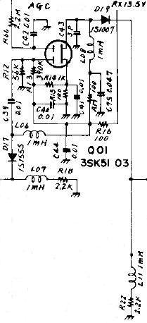
The RF amplifier is a 3SK51 in a rather interesting circuit. Normally, one would allow the transistor to self-bias, by grounding the gate and using the voltage drop over the source resistor (caused by the source / drain current) to effectively cause a negative voltage Vgs (it's a depletion mode transistor, Vgs should be negative). But in this case, both the gate and the source are biased using voltage dividers. This is not unacceptable, see Siliconix AN102 page 4, "Biasing for Device Variations". The 3SK51 (here's the best online datasheet I could find) is specified with Idss = 7 to 25mA and Vgs(off) = -0.3 to =3.0V. This is a huge spread, and explains the biasing scheme, maybe. Note that while Vg1 is constant (at about 1.5V), Vs can be anything from about 1.7V (Id = 7mA) to 2.9V (Id = 20mA). This sets Vgs at -0.2V to -1.4V which sounds mostly right. I'm not convinced that I fully understand this, but then, I don't have a clue what the 3SK51 manufacturing tolerance curves look like, and I can only assume the Yaesu gnomes knew what they were doing. Anyway, I replaced the 3SK51 with a transistor I got off eBay, supposedly a BF964N. This brought the S-meter reading for the marker up to S8 or so, not the S9+20dB the Service Manual indicates. I thought that maybe the gain was a bit low because of the biasing, so I removed R13 and R14, but this made little to no difference.
|
If you have a piece of electronics from the eighties, be it a radio or a Macintosh, replace all the electrolytic capacitors. The Instruction Manual lists the following.
| 1u 50V | 17 |
| 2.2u 50V | 4 |
| 3.3u 50V | 1 |
| 4.7u 50V | 1 |
| 10u 10V | 1 |
| 10u 16V | 26 |
| 10u 25V | 2 |
| 22u 16V | 6 |
| 33u 16V | 29 |
| 47u 16V | 3 |
| 47u 25V | 3 |
| 100u 16V | 5 |
| 330u 16V | 1 |
| 330u 25V | 1 |
| 470u 6.3V | 1 |
| 470u 16V | 1 |
| 1000u 16V | 2 |
| 2200u 25V | 2 |
It seems that the relays sometimes give trouble, and replacements can apparently be difficult to find.
|
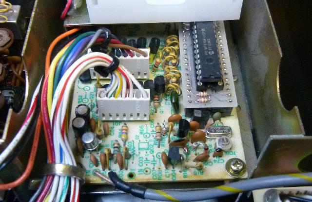
This is RL01 on the RF board. It's controlled from the ACC-2 (transverter) socket and turns
the RF Out (J03) on while turning the power (bias) to the final amplifier off. Like the
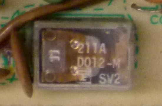
relays on the AF board, the Noise Blanker board and the Clarifier board, it's a Fujitsu
FBR211AD012-M
(which has been discontinued since 1998).
I scrounged around a bit and it looks as if the TE V23101-D0006-A is a drop-in replacement. There are also physically smaller relays available that can be made to fit, for example the Fujitsu SY series or the Omron G5V-1. The DMS board has a similar relay, FBR211AD009. This is just a 9V version of the above. |
The Service Manual states that the RF Motherboard RL901 is also FBR221D012. This is not true (or at least not in my case). The relay on the RF Motherboard is a DPDT unit, 0.3" x 0.6".
The main chassis relays RL1 and RL2 are FRL-263-D012/04CS01 and RL3 is FRL-263-02CK-OD. The FINDER 55.34.9.012.0040 is apparently a replacement.

If you're having relay problems, this is because relays want a small DC current through them to prevent contact oxidization. You can clean the contacts, but the ultimate fix is adding RF chokes and a resistor to bleed a small current (1mA should do) through the contacts.
November 2017: Charles ZS1CJO gave me a basket-case FT-107.
I got smoke out of the finals when I tried to fire it up with a battery. If it works after replacing a fuse that will be your good luck ;-)
|
|
Back | (This page last modified 2023-10-31) |