<- Back root
Eurelec vacuum tube tester
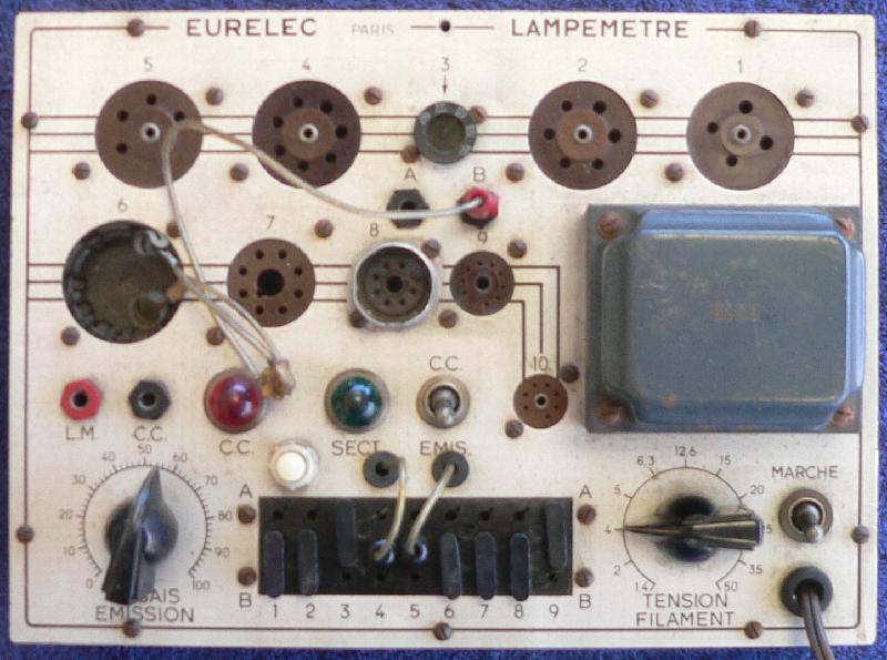
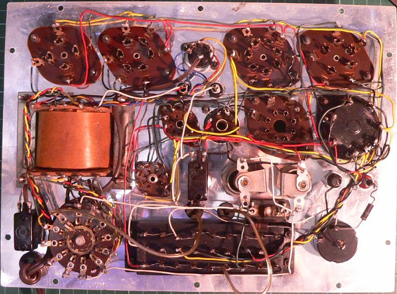
Here's a link to the history of
the Eurelec vacuum tube testers (in French,
here's a Google translate version (2016-01-25)).
According to this page, these testers were known as Euratele in Germany and Elettra in Italy.
This explains the similarity to the Euratele unit shown on
Jogi's
page (in German,
here's a Google translate version (2016-01-25)
-- Thanks to Carsten Falck for the pointer).
Based on this, here's what I could figure out:
- These units were built by the students at the radio school (I inherited this one from a
French fellow my grandmother knew, along with a
signal generator I will
undoubtedly find again some day).
- It's used with a multimeter they undoubtedly also built. The multimeter has "LM" and
"CC" terminals which are connected to the "LM" and "CC" terminals
on the Eurelec tube tester ("LM" = Lampemètre, the German version terminal is marked
"RP" = Röhrenprüfgerät).
- This multimeter has an FSD of 1mA and a series resistance of 72 ohm (in this mode).
- The multimeter scale is marked "BAD" to about 40% of FSD and "GOOD" from 56% up.
- The multimeter is bypassed by the "Emission" potentiometer, so that the multimeter
measures a percentage of the current according to the potentimeter setting.
| Pot Setting | Rbc | % Current through meter |
|---|
| 0 | 100 | 37% |
| 10 | 90 | 34% |
| 20 | 80 | 32% |
| 30 | 70 | 29% |
| 40 | 60 | 26% |
| 50 | 50 | 23% |
| 60 | 40 | 19% |
| 70 | 30 | 15% |
| 80 | 20 | 10% |
| 90 | 10 | 5% |
| 100 | 0 | 0% |
- You have to look up the settings in tables in the
user manual.
This gives you the potentiometer setting and the connections for any specific vacuum tube.
"A" is the high-voltage supply and "B" is 0V.
|
Cathode |
Grid 1 |
Grid 2 |
Grid 3 |
Anode |
| Diode |
B |
|
|
|
A |
| Triode |
B |
B |
|
|
A |
| Tetrode |
B |
B |
A |
|
A |
| Pentode |
B |
B |
A |
B |
A |
- You can turn the pot to 100%, use a standard multimeter and scale the display to give you
the current through the tube. Or you can build a meter just for this purpose, schematics
on the two websites above.
- You can also check to see whether there are shorts between the anode and grid(s) and the
cathode. Switching to "CC" ("Court-Circuit" i.e. short circuit) mode
connects 6.3V to the "A" rail with the red lamp in series. A short between
"A" and "B" will light the lamp.
http://radioman64.e-monsite.com/pages/mes-depannages/lampemetre-eurelec-v1-0-essais-et-ameliorations.html
Euratele AM-FM-ABGLEICHSENDER
I took these pictures at the CTARC March boot sale.
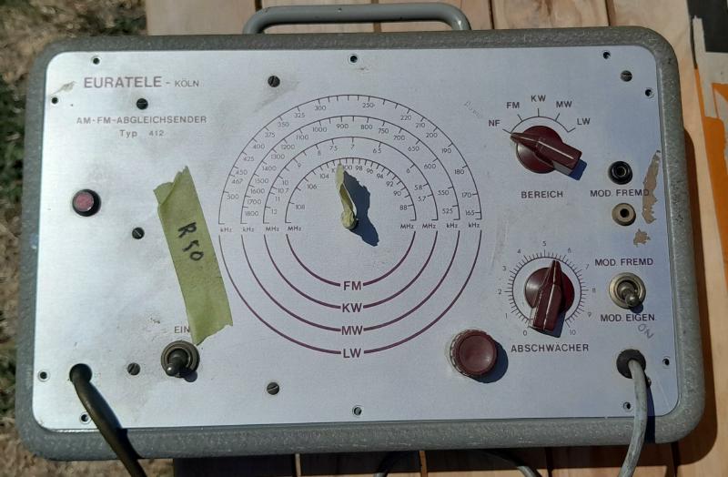
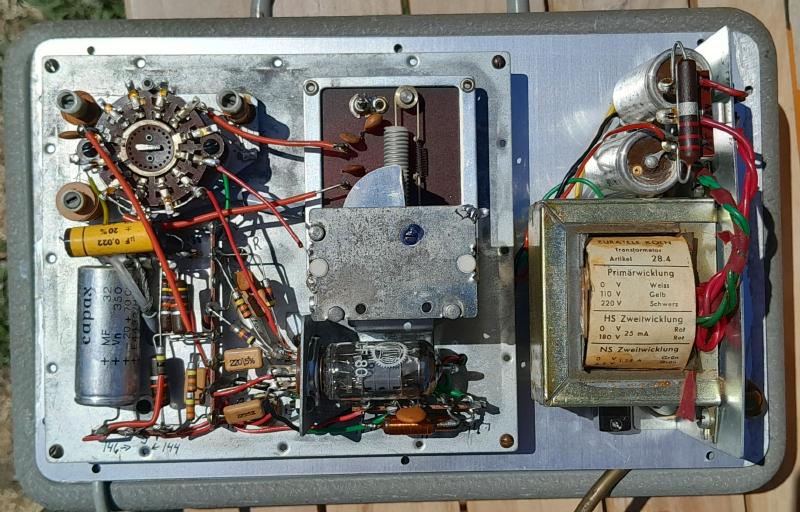
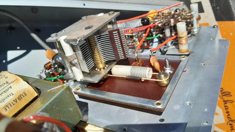
Note the VHF tuning arrangement.
|
![[Image] Hit Count](/cgi-bin/Count.cgi?df=wrm-zs1ke-Eurelec.dat) hits since 2015-03-11.
hits since 2015-03-11.
|
Back
|
(This page last modified
2025-03-02)
|


