
Front view of the combination (B56)
From the defenseWeb fact file on SA military radios:
| Power output | Letter | Typical size |
| Less than 10 Watt (W) | A | Manpack |
| 10-100W | B | Manpack/Portable>/td> |
| 100W-1000W (1kW) | C | Vehicle |
| 1-10kW | D | Vehicle/Static |
| Above 10kW | E | Static |
Radio letter designations. Note these are allocated by power output.
| Number | Frequency range |
| 10-39 | MF/HF: 300-30,000kHz |
| 40-79 | VHF: 30-300mHz |
| 80-99 | UHF: 300-3000mHz |
So an A55 would be a sub-10W VHF radio and a B56 would be above 10W, still VHF.
Specifically, the A55 is a 1.5W transceiver for 26-76 MHz. It runs off a 16.5V battery, which clips to the back (more specifically, the SO55 transceiver with the battery pack fitted is called an A55).
When it is unclipped from the battery and clipped into the SO56 power supply / amplifier unit, it becomes the B56 with switchable output up to 25W.
The B56 entered service with the SA(N)DF in the mid-1970s and they are still in service in some places, although they are being replaced slowly.
Front view of the combination (B56)

SO55 - A55 less battery pack The "Tone / Toon" setting enables
a 150Hz subtone. On the "Noise / Ruis" setting this is disabled.

Ten preset channels

The battery or external PSU contacts

SO56 - the amplifier unit

Inside, top view. Note date stamp "14 Nov 1981"

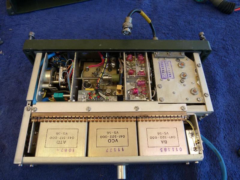
Inside, bottom
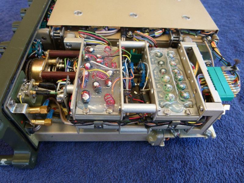


All the modules are screwed down.

The screws are captive and it looks as if
all the modules are hermitically sealed.

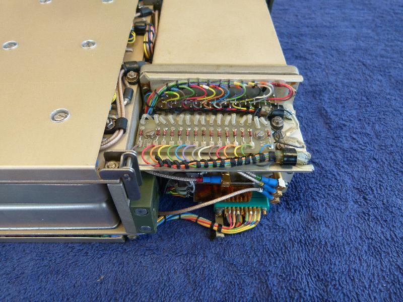
Here you can see all the modules

Wiring between the modules

On my radio, these two wires are desoldered from the connector
and insulated in a most definitely non-mil-spec manner.

Power connector
Open

This is not good. The reverse diode is cracked and disconnected from the pin.
Looks like someone reversed the power to the unit. The good news is that there's
also a series diode so the electronics should not have been hurt.

Look at the size of that keyway. Definitely not troepie-proof.

The B56 part of this thing looks like it's been in the wars. In all honesty, it might have been.

The second dent is actually worse. It prevents the unit from sliding out of the enclosure.

Easily fixed with a G clamp.
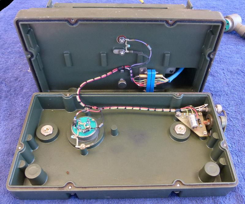
Inside view

The solder joint in the centre of the pic is where the on/off switch should go. On the left there's
an actuator and on the right a switch
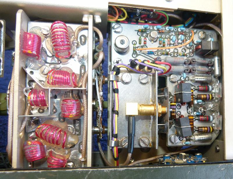
and bandpass circuitry. Both are suspended between leaf springs.

Open. You can see the leaf springs on the right hand side.

The wiring is gorjuss.
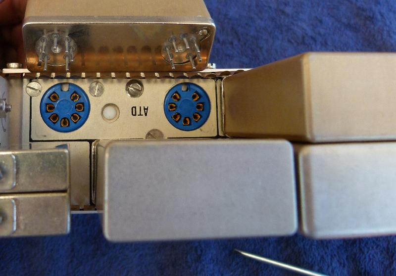
These modules use 7 pin miniature glass tube / valve sockets.

The A55/B56 can optionally be fitted with a frequency hopping module. This picture from ZS6CD shows the ten channel preset module and the frequency hopping module that would be installed in its place.

There was also an A55H model where the frequency hopping module was built in. According to ZS6CD it was never sold.
|
|
Back | (This page last modified 2015-12-29) |