Electronics

Peek & Poke


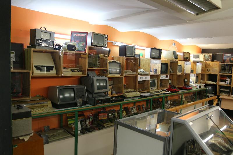
Rijeka is home to quite a large computer museum (as these things go, and measured in number of computers, not floor space). You will find the expected Apple / Atari / Commodore / IBM PC and clones… but those don’t interest me so much. What is interesting is the cold war East Bloc stuff that we never got to see or experience in the West.

Unfortunately a lot of the exhibits are behind glass and don’t photograph well.

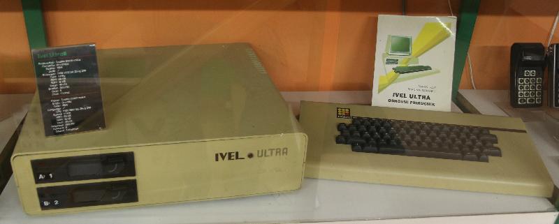
This is an Ivel Ultra, a Croatian Apple II compatible computer designed by Branimir Makanec and developed by Ivasim Elektronika (in Ivanic Grad close to Zagreb) around 1984. It has a Z-80 (for CP/M) onboard like Franklin did with the Ace 1200.

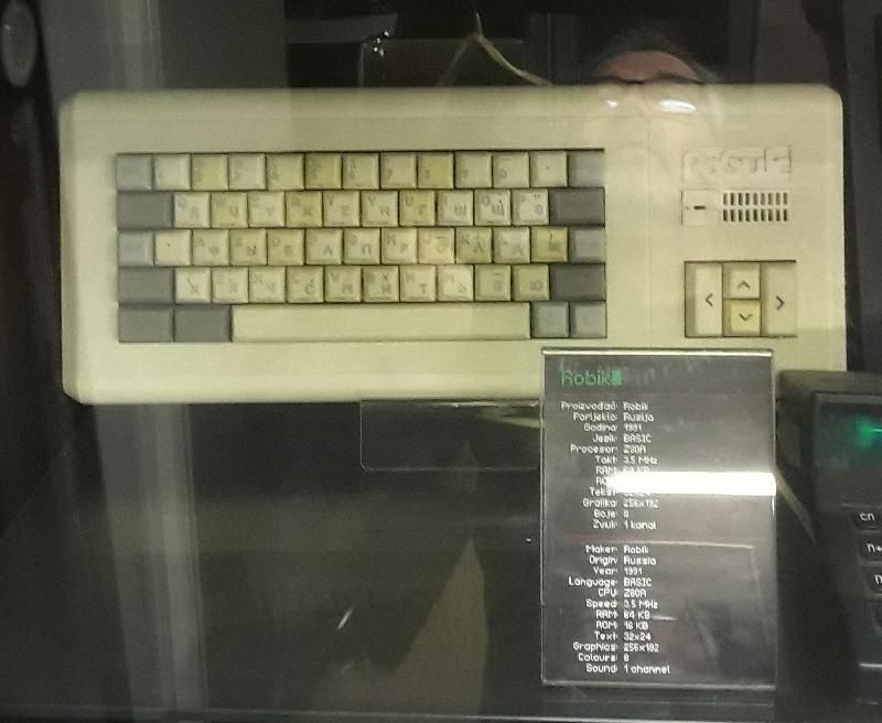
The Robik is a Soviet ZX Spectrum clone produced between 1989 and 1994 in the Ukraine.

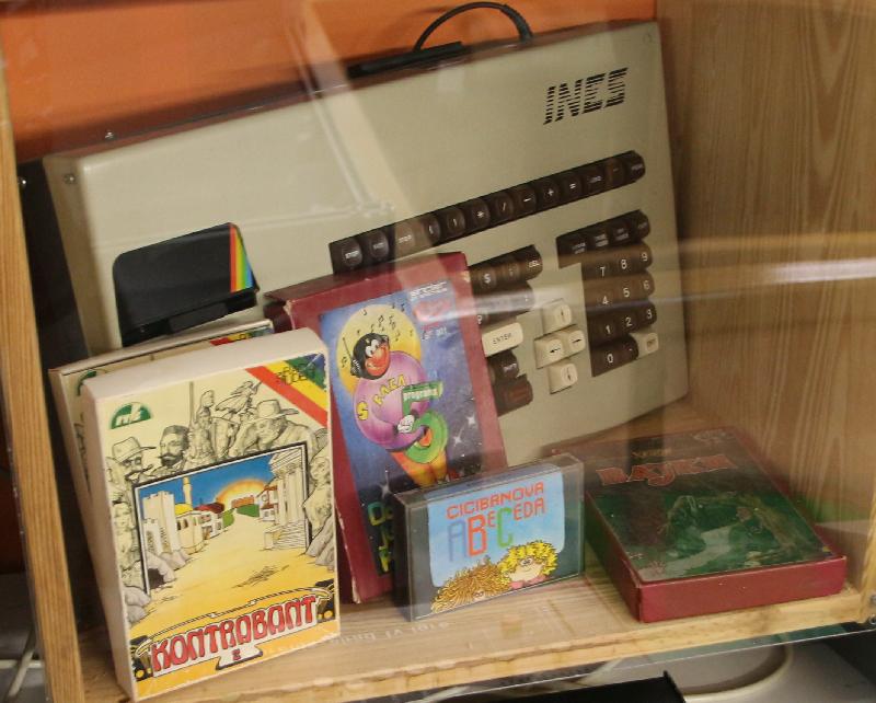
Spica Ines: A decent keyboard for your ZX Spectrum. And a bare PCB would be easier to import as “washing machine parts” than the whole computer…

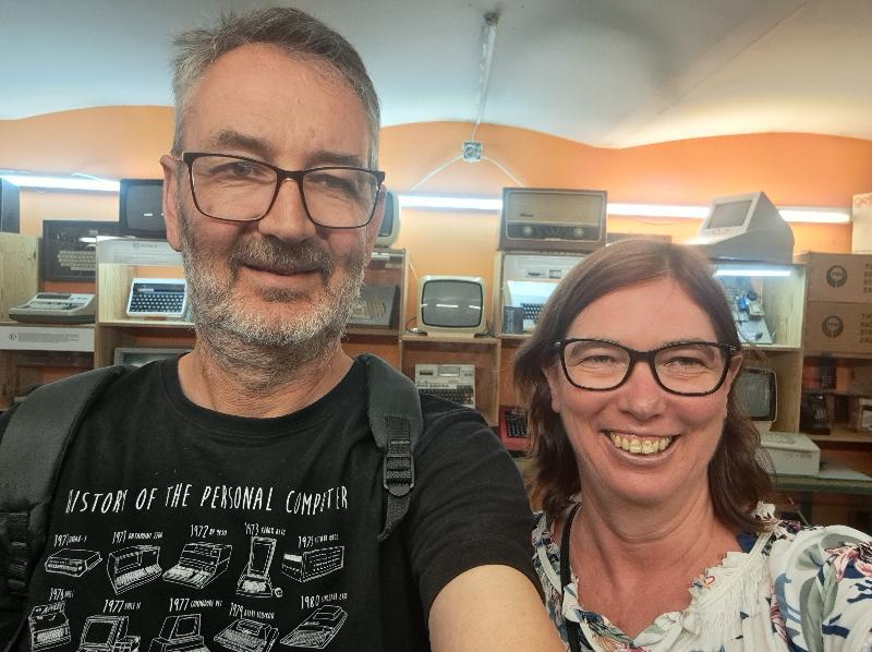
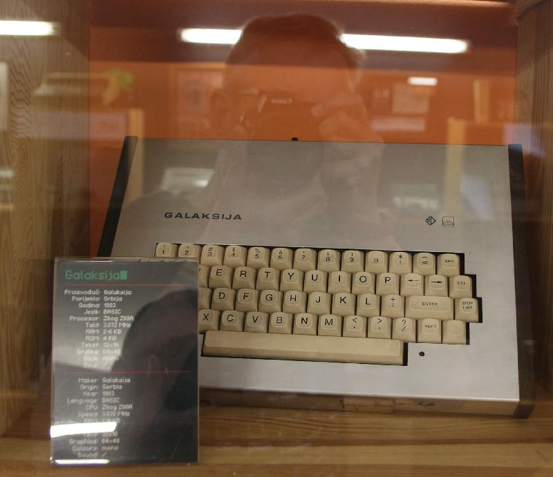
Much more interesting (and also an unavoidable self-portrait) is the Galaksija.

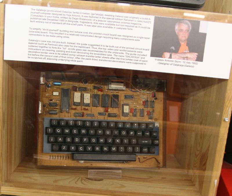
In 1983, Voja Antonić designed the Galaksija, using a Z-80 processor, some interesting hardware and some hectic software to render the screen directly from memory using interrupts and code that does nothing in a very specific way while using the Z-80 RAM refresh function to pipe the scan lines to the monitor.

The design was published in the October 1983 issue of Galaksija magazine (hence the name) and at least 8000 of these things were built. At least.

Several versions of the PCB has now been recreated, and there’s even a way to get graphics if you have enough memory.

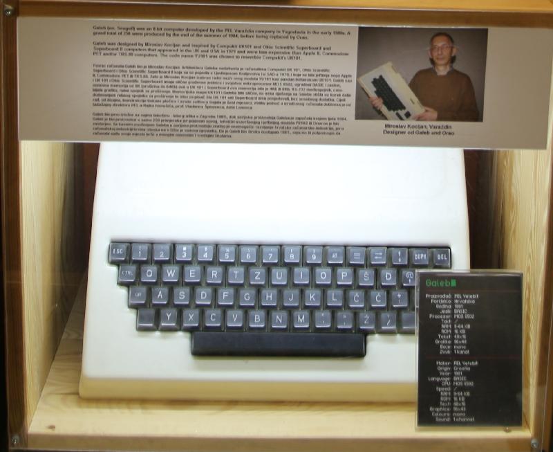
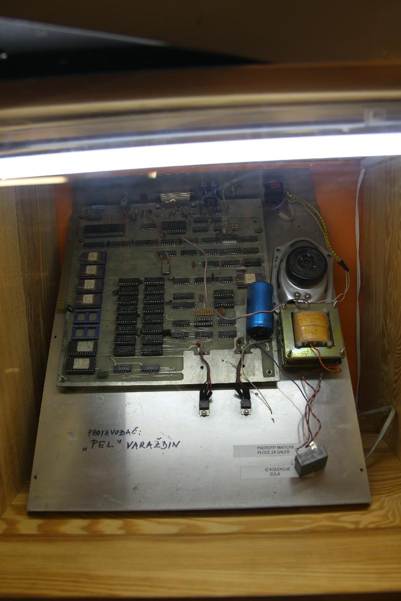
Then there are the commercial “home” computers. The Galeb (“Seagull”, codename YU101) was an 8-bit computer developed by the PEL Varaždin company in the early 1980s. Only 250 were produced by the end of the summer of 1984, before being replaced by the Orao. It’s a 6502 machine “inspired by the Compukit UK101” but if this Ferguson Big Board “(C) Mikro Slovenija” is an indication, it might have been very similar indeed.
One of the Galeb prototypes.

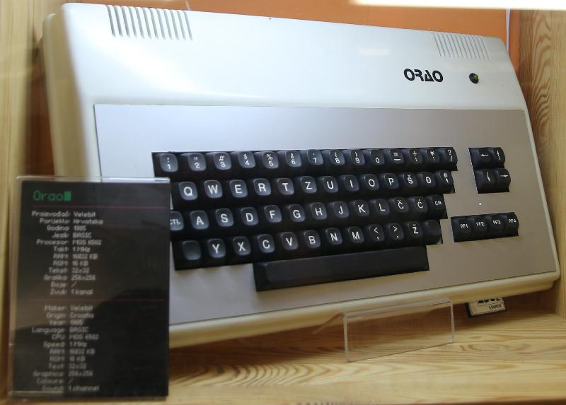
The Orao (“Eagle”) replaced the Orao. Still 6502 based, it was developed by PEL Varaždin in 1984. It was used as a standard primary and secondary school computer from 1985 to 1991.

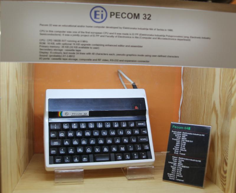
The Pecom 32  and Pecom 64 were 1802-based educational/home computers developed by Elektronska Industrija Niš of Serbia in 1985. Both had 32k RAM and 16k ROM, but the Pecom 64 supported colour while the Pecom 32 was B&W, as far as I can tell.

These used the standard 1802 (CDP1869 + CDP1870) VIS display system.

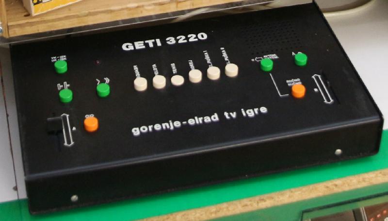
The GETI 3220 is an AY-3-8500-based pong game made by Gorenje, who is better known for their household appliances (our fridge in Globoka is a Gorenje).

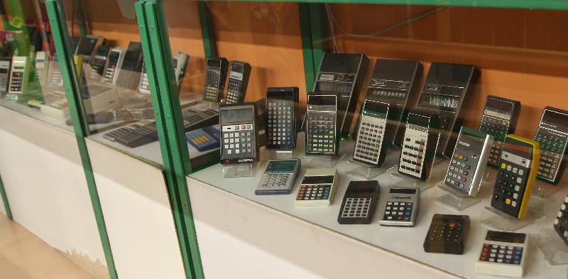
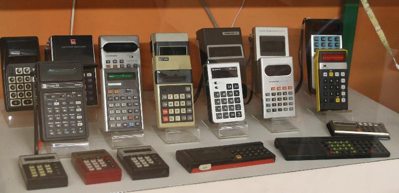
They also have calculators.

Lots of calculators.

I have a Triumph/Adler 108T, that Triumph looks like an 81S.

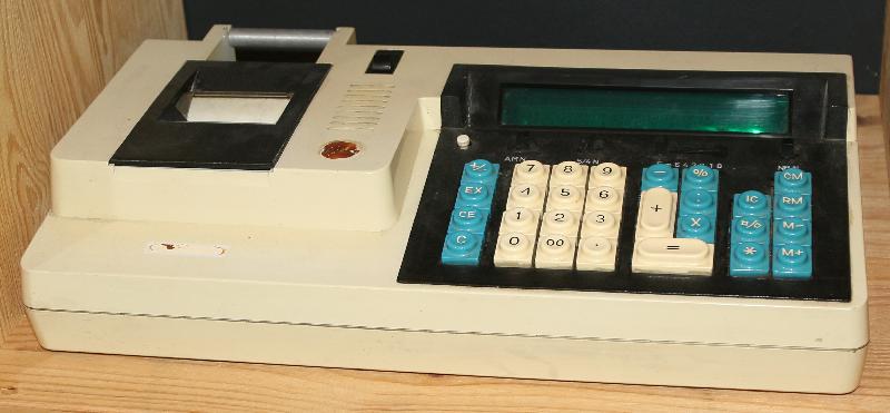
I also have the exact same Tvornica Računskih Strojeva TRS612 calculator, although mine is missing a few pieces. Made in Zagreb in the seventies.

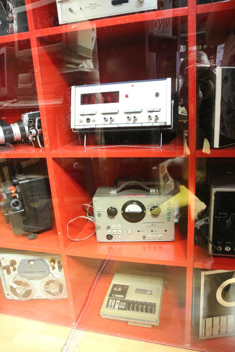
They also have TVs, and audio equipment, and cameras, and test equipment. And I have the exact same Philips PM2421 Nixie-tube multimeter (top center of pic).

They cram a lot into 300 square meters.

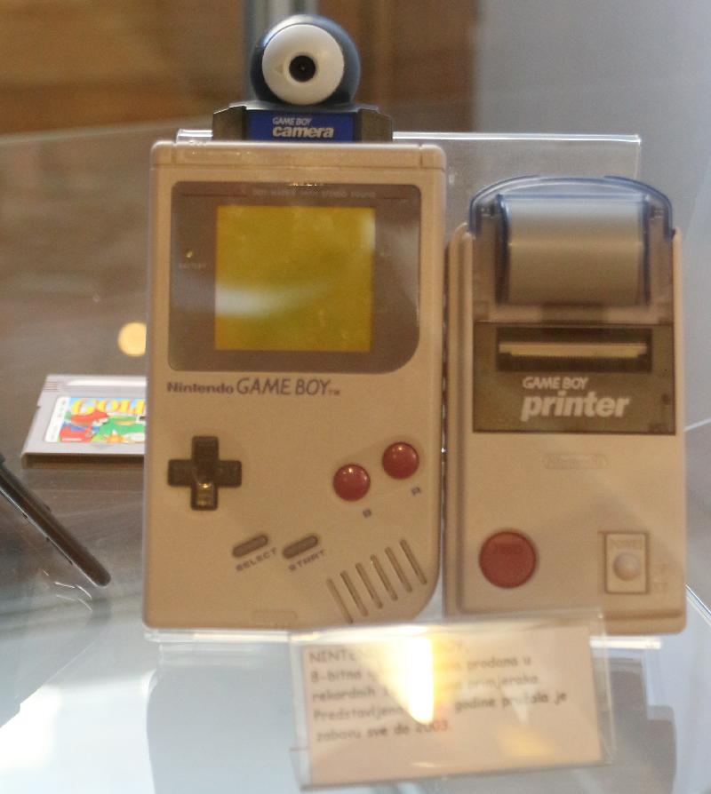
I knew there was a camera, but I never knew there was a printer for the Game Boy. You could take a picture, print it out (in glorious monochrome) — the electronic version of Polaroid.

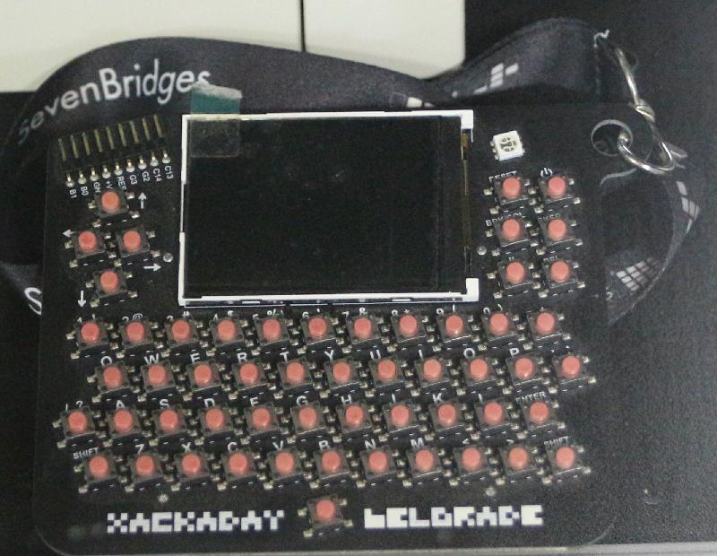
A bit more modern but still historically significant — the badge for the Hackaday Conference in Belgrade, 2018.
The website mentions that they’re looking for bigger premises. I will have to go back someday.


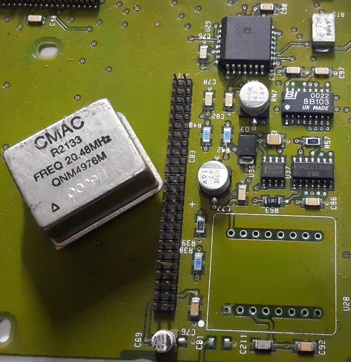
CMAC R2133 20.48MHz TCVCXO

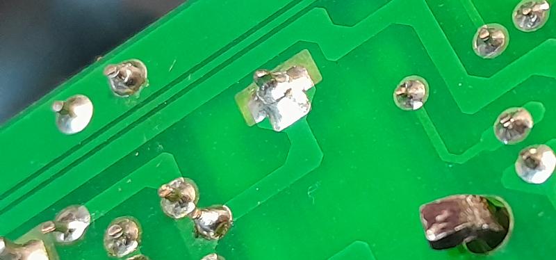
I have two PCBs from a piece of defunct Nortel equipment with this oscillator. CMAC R2133 Freq 20.48 MHz. Looking at the circuitry around it, there’s a 16-bit DAC (AD7846), a 5V regulator (78L05) and a buffer (74F00). Google could not find me a datasheet, so I removed the oscillator to trace the pinouts (Nortel used the outside layers as groundplane, you will see nearly every trace goes from a component to a via. Makes it difficult).

Pin 1 is 0V, pin 2 is the output, pin 3 is 5V, and pin 16 is the control voltage from the DAC which is configured to supply 0-5V out via the 51R1 resistor R40 and a 47u capacitor C77. The output goes to pin 2 of the 74F00 via 33R2 R53.

I posted the above pic to Facebook, within an hour or two someone sent me the datasheet (well, the Nortel spec sheet, which is basically the datasheet in reverse). It is indeed a TCVCXO, pinouts as I’d already determined (pins 4-15 are N/C), giving -10 to -15 ppm with 0V on the control pin and +10 to +15 ppm with 4V on the control pin.

Stick this thing through an 11 stage binary counter and you get 10 kHz, add a PIC and a GPS and it could be the most accurate thing on your bench.

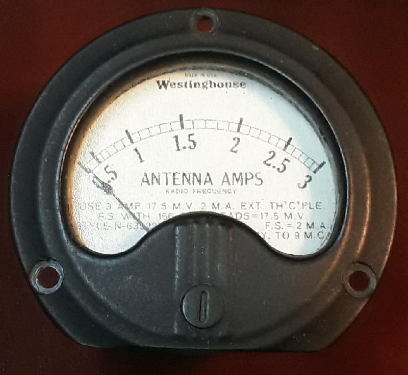
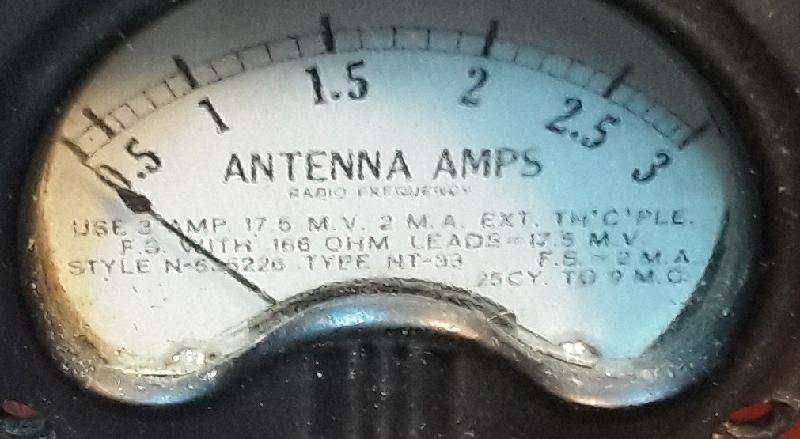
Westinghouse NT-33 Antenna Ammeter

From my stash of interesting stuff. I know very little about measuring antenna current, I’ve never seen it covered in a Radio Amateur Handbook or the like. Not even my 1948 edition.

The meter face (note the non-glare glass) reads “USE 3 AMP 17.5 M.V. 2 M.A. EXT TH’C’PLE. F.S. WITH .166 OHM LEADS = 17.5 M.V. STYLE N-635226 TYPE NT-33 FS = 2 M.A. 25 CY TO 9 M.C.

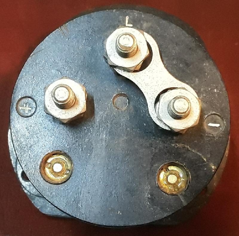
It has three terminals and I have no idea what “L” means.

Turns out “L” is connected to the back of the meter face. Still don’t know what it stands for.

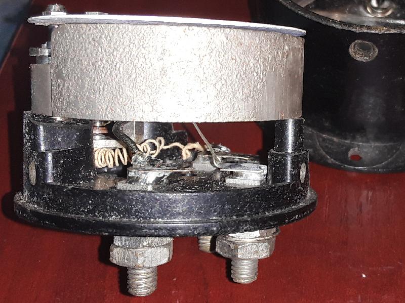
Anyway, it’s a non-linearly calibrated d’Arsonval movement with a (measured) internal resistance of 8.5 ohm and an FSD of 2mA. 17.5mV over 8.75 ohm is 2mA, so depending on whether the 0.166 ohm lead resistance is for one or both wires, the internal resistance should be 8.58 ohm or 8.42 ohm so yea, the complete meter spec is written on the meter face if you know what to look for.

It should look good in some retro kit, even if I have to interface a PIC to the back of it to get the calibration right.

Silicon mumbo-jumbo

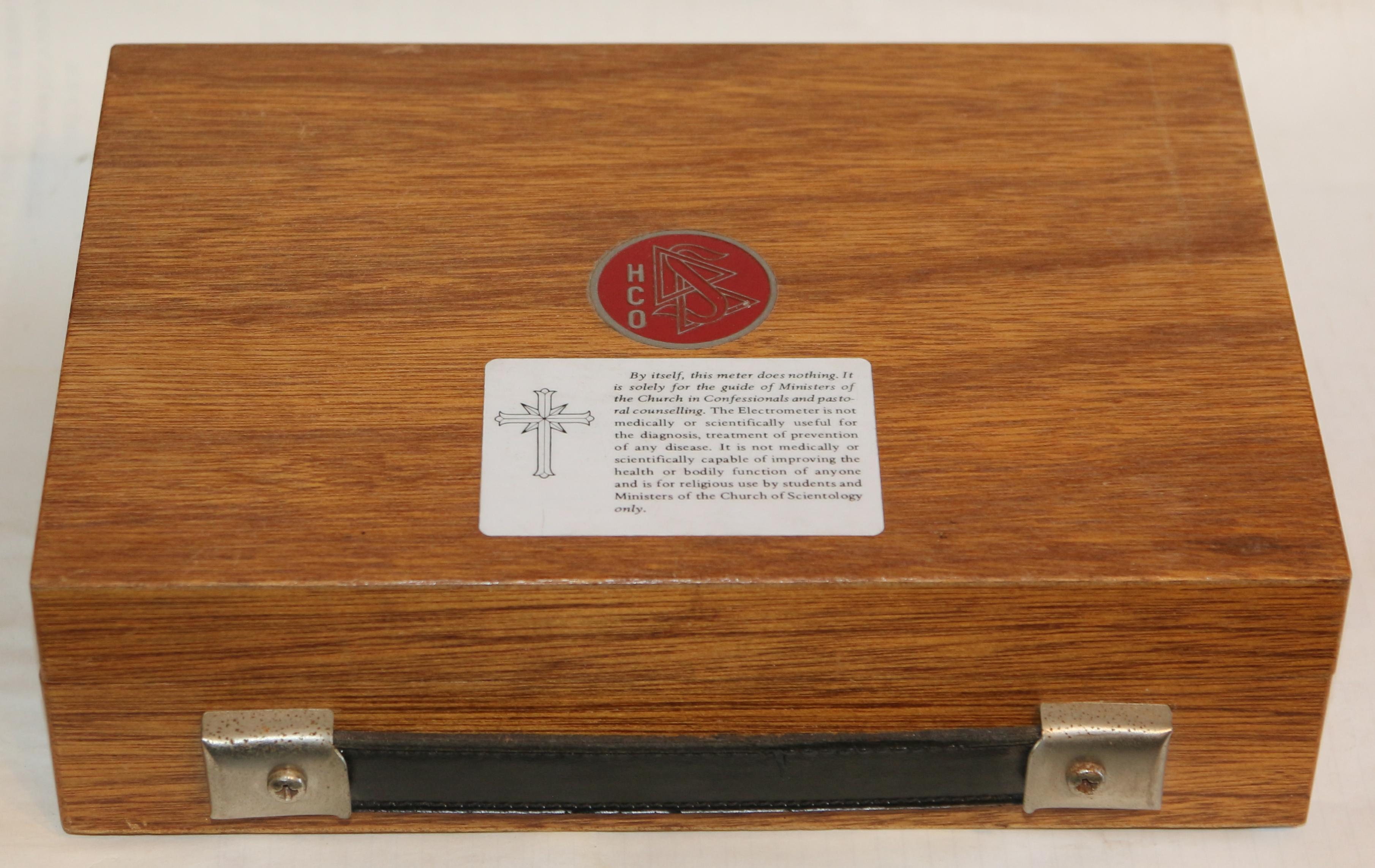
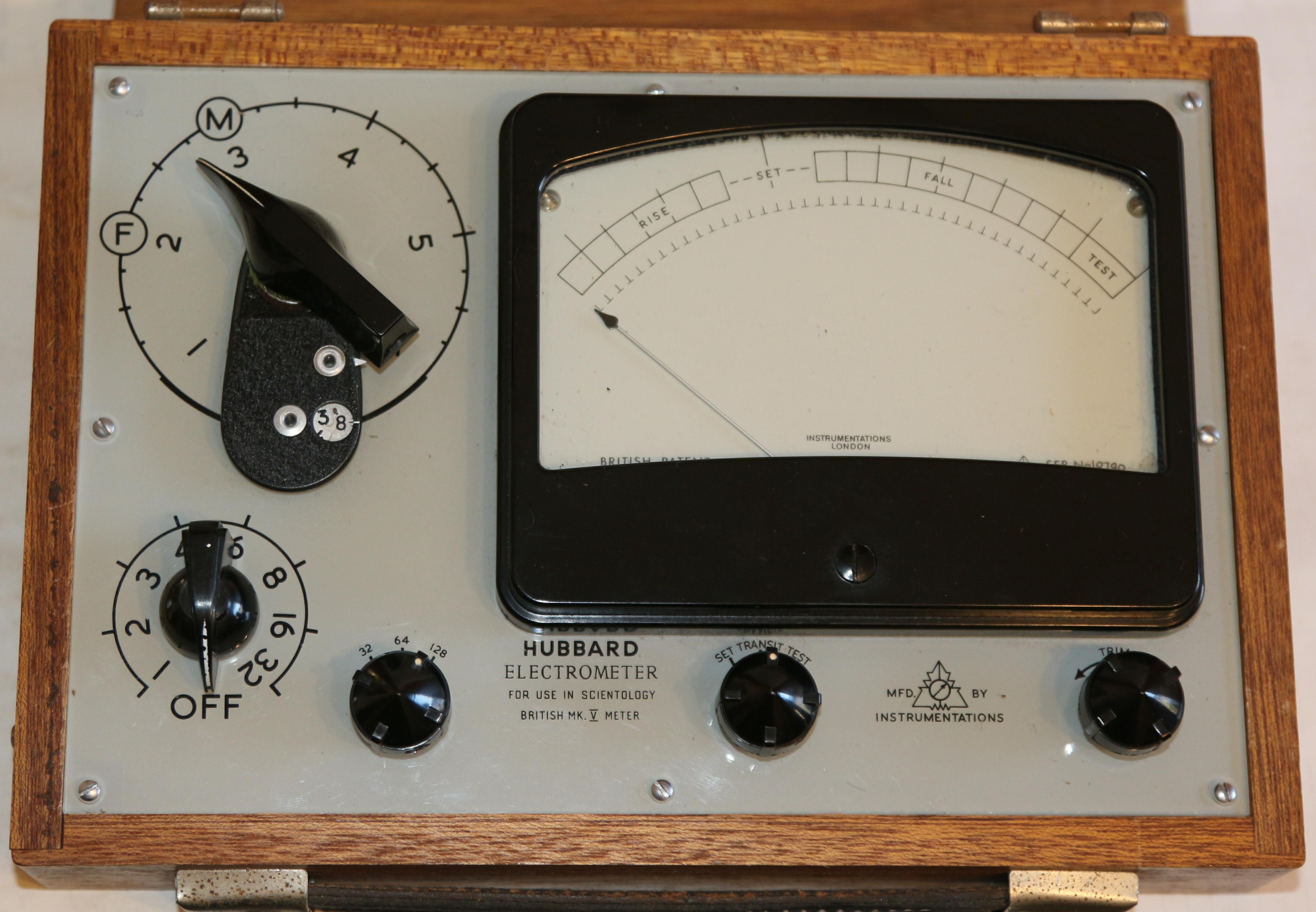
So this thing crossed my path.

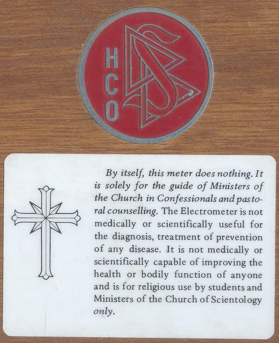
I suppose that’s as much of a disclaimer as you’re going to get.

Because it’s pure snake oil.

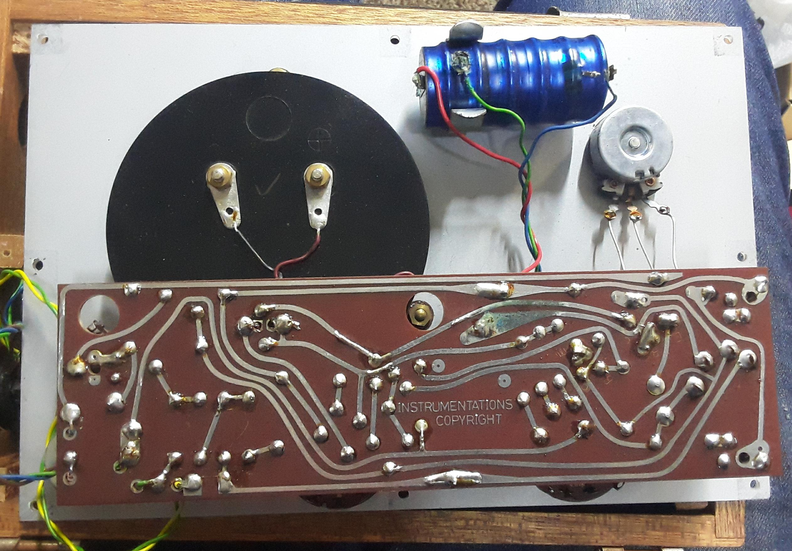
Of course I took it apart and reverse-engineered it.

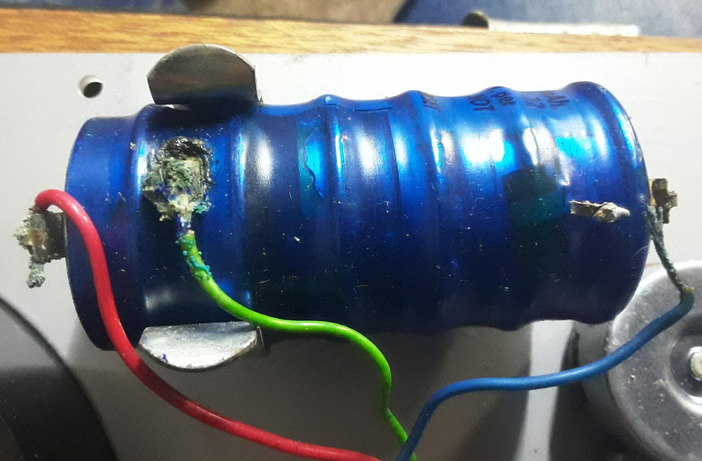
The battery was a bit dodge so I disconnected it.

Someone else had been here before.

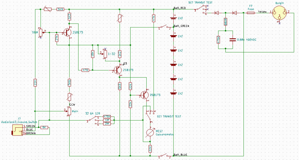
The schematic is very similar to the one on the cs.cmu.edu web page. The power supply is… interesting. Unless there’s an external transformer that I don’t have?

Logic Probe

There’s a kid around the corner who is building a Z-80 computer on veroboard.

This is not his story.

But in helping him I realised he needed a logic probe. This is that story.

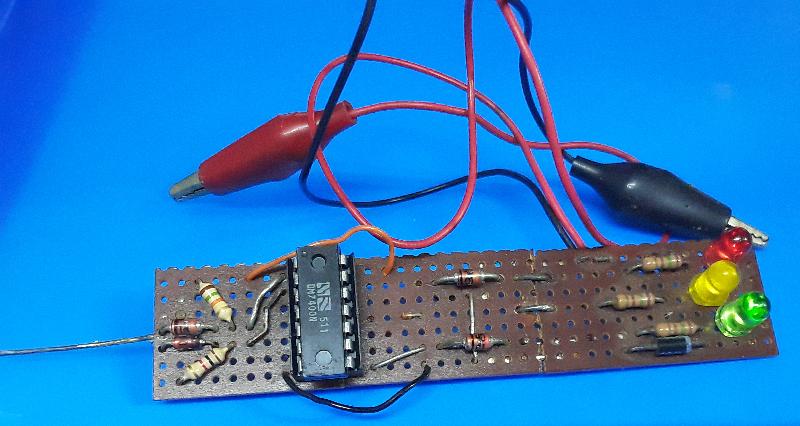
I built this logic probe a … long … time … ago. Late seventies, I think. You can see where I cut it down the middle to fit in a pill bottle, but I straightened it again later.

And I could lay my hands on it when I needed to, a week ago. Yea, I don’t throw stuff away. Especially not useful stuff, and a logic probe counts as useful. I had to replace the 7400 which is now in a socket, back when I built it a socket would have been a luxury.

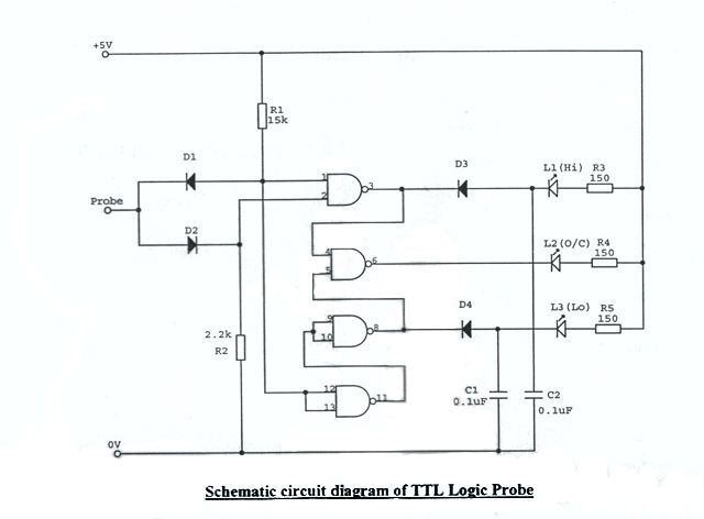
Above schematic from stackexchance. I have no idea where I got the original schematic from, but this is it, except that my Edit (2024): Well, turns out I keep good records when I remember where to find them, I got the original schematic from Practical Electronics, March 1983, it was submitted by G. Coleman from Rochester in Kent, with R2 = 1k and C1 and C2 = 1u in his schematic, same as my build.

And when we built one for Z-80 boy the other day, we found that R2 should indeed be 1k, because otherwise it doesn’t work right.

I also added a diode for reverse-voltage protection which is not a bad idea.

There are of course many other, better designs out there (electronicsforu.comelechelp.com, circuitfee…), including one in Everyday Electronics of September 1980*. But this one is simple and it works.

* I “subscribed” (in that my parents would give me the money every month and I would walk down to the CNA on Voortrekker Road and buy a copy, which they reserved for me) to Everyday Electronics from September 1978, or at least, that’s the earliest cover I remember.

When your failure detection system… doesn’t actually fail.

Couple of years ago, I repaired a NAD T751 which turned on and then immediately off again. These NADs have a protection circuit that shuts the amp down if something is wrong, and in this case, the protection circuit was at fault.

So when my brother spotted a T760 with exactly the same problem, he bought it, figuring that this was a solved case.

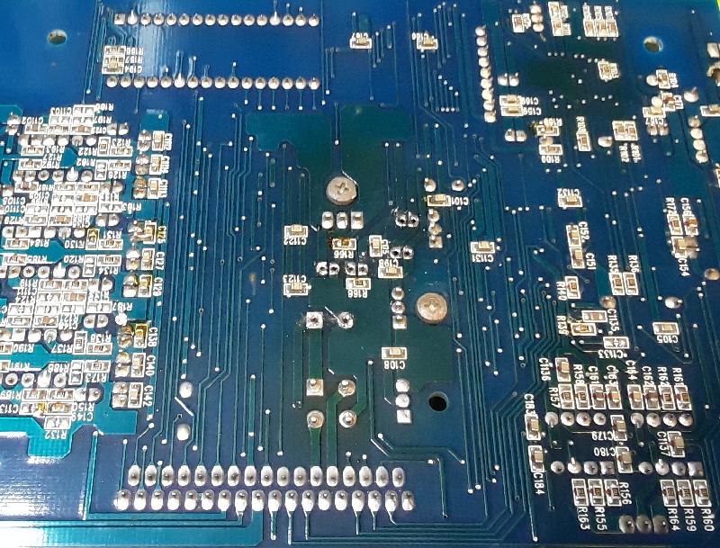
This turned out to not be the case. While the T760 is almost identical to the T751, this one lacks the bodge that caused the problem last time. And while the prime culprits (C173, C174, C176, C199 on the AC3 board) were all out of spec (measuring 70pF to 10nF), replacing them did not solve the problem.

(If your PCB is discoloured around the voltage regulators, the amp ran hot for long, and that dries out the caps).

Anyway. so I went where I should have started, and measured the offsets on P501, P502, P503, JP801 and JP802 (representing the amplifier quescient current).

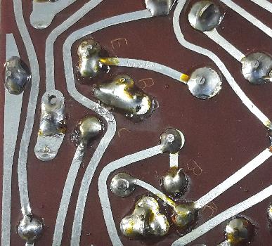
And that explains it (even if it’s a b*tch to get at).

Attended to a couple other suspicious-looking solder joints, buttoned the whole thing up again. Offset on the centre amp (the one which had the bad joints) doesn’t want to come down below 2.7mV so it’s going to run a bit hot, others all at 2.0mV (over 0.22 ohm, so 9mA idle current).


Sometimes it’s better to remain quiet.

None of these answers is useful. I’m fully expecting the next comment to be a warning not to solder without adequate ventilation.

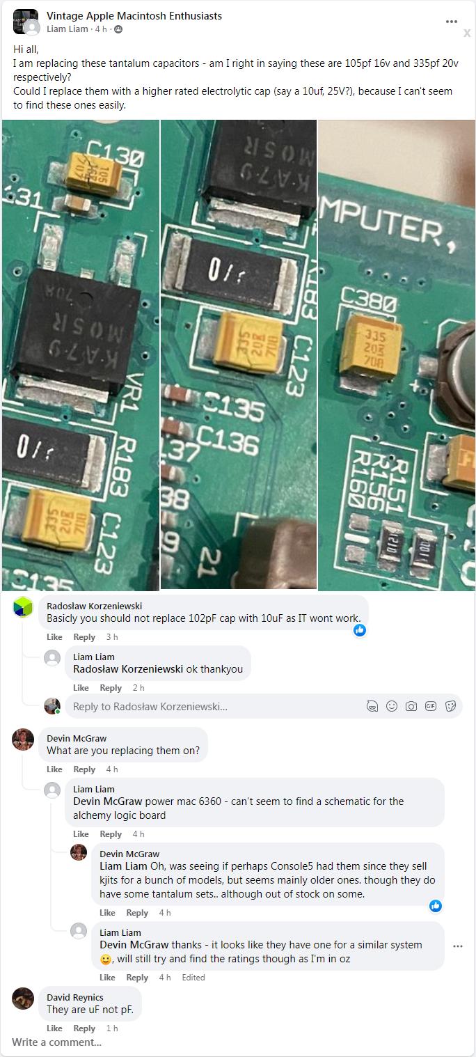
(For the record, 105 = 10 and 5 zeroes, just like a resistor, so 1000000 pF = 1 uF. And yes, 15 is the voltage. Also, google “what is the value of a capacitor marked 105” gives the correct answer straight off the bat. People. Feh).

Flea Market Find

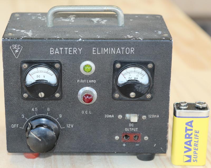
The Cape Town Amateur Radio Club traditionally has a flea market at the beginning of March. This year I didn’t take anything to sell, and strictly speaking I didn’t buy anything either — I said “ooh nice!” the fellow said “take it” so I gave him R20 and said “take it”.

“SEC” is probably Something Electronic Company, there’s a “JAPAN” sticker on the back.

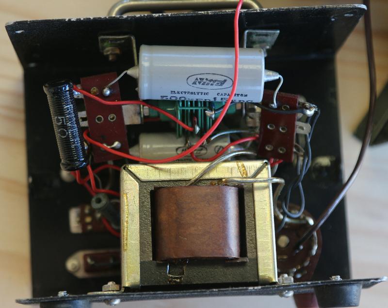
Inside is fairly mundane, a tapped transformer, a selenium rectifier which dates it to the late fifties / early sixies, a pi filter with two caps and a resistor, a series light bulb “O.C.L.” and a couple meters and associated resistors.

It’s pretty, it’s going on the shelf.


Really large PCB

If you need an oscilloscope, or you have an oscilloscope that needs a service, Peter is your man*. I bought an Elteknix OS 620 from him, gave him my Hitachi V650F to service.

In his stash of stuff he had a large PCB with a 68000 on it. Obviously an arcade game of some type, I recognised the JAMMA connector. Gave me a bad case of the 10th Commandment. So he gave it to me.

Apart from the 68000 there’s also a Z80, in close proximity to the only surface-mount IC on the main PCB. Said IC is a MSM6295, a sound chip used in many games, so this does not narrow down what we actually have here. But some searching for the text on the ROMs pointed me at this ROM image, and some further searching gave me this auction.

So it’s a bootleg Street Fighter II.

It’s also to far gone to save, IMO.

Interesting mix of chips, very heavy on the programmables, with lots of GALs, an OTP 27512 and three HY18CV8 EEPLDs. I found the array of 74597 shift registers interesting, I wonder whether they shift the content of the rather large (10 Mbit) ROM / EPROM array straight out to video (maybe to create the background).

And interesting to note, it’s all on two PCB layers.

So now I’m conflicted as to whether I should strip it for spares or mount it in a lightbox for display.

*Assuming you’re in the Cape Town area, that is.