House

So much for their one saving grace

As hardware stores go, the Builders Warehouse in Tokai is… so/so.

They’re large, and have a selection of stuff, but there’s also a lot of stuff they don’t have. And their prices are good, sometimes, but some other stuff is a complete rip off.

Their sales staff range from pretty good… to useless. The paint guys are great. The electrical guys are not bad at all. On the other hand, the bunch hanging out by the tool section have no clue as to what they’re selling, and can’t offer any advice. And the dude on the cut board counter should be drawn, quartered and shot.

<me> “Excuse me, how much is your bullnose postform countertop (points at stuff on shelf one meter from dude) in Etimo?”

<dude> “I can’t tell you that we have to order specially” *wanders away*.

Not “can I get back to you?”. Not “approximately $bignum but I’d have to confirm”. Oh no.

But despite this, I spent probably R50k with these guys the past few months.

Because they were open until 19:00. Convenient. But this changed — they now close at 18:00, just like all the other hardware stores. So they’ll be seeing a lot less of me.

Oh, and they’re also a gunfree zone. In my friend Richard Boothroyd’s words, “not when I’m there, they’re not”.

Geek Alert : Some basic jacuzzi mathematics

It takes one kilo-calorie to heat 1 litre of water by 1 degree C. A calorie is 4.184 joules. In science-speak : “The specific heat capacity of water is 1 cal/gram-C or 4.184 Joule/gram-C”.

A Joule is also a Watt-second. Which relates to the well-known kilowatt-hour by a factor of 3 600 000.

In mathematical terms :

Q = mc(DeltaT) : m = mass, c = specific heat capacity, deltaT = amount you want to heat the water (or anything else) by. The important thing is that all the units match, to get Q in Joule you need c in Joule/gram-C.

The optimal jacuzzi temperature seems to be 39C (102F). So if the water is at 15C, deltaC = 24.

And thumbsuck : the typical jacuzzi is around 1000 litres.

Q = 1000 x 4184 x 24 (Note the sly dropping of the decimal from 4.184 — this is because we’re working with litres not grams, a liter of water weighs 1000 grams) = 100416000 Watt-seconds = 27.89 kWh. Which at the current 47.38c/kWh equates to just over R13.

And with a 4kW element, this will take almost 7 hours. Of course this ignores any losses, anything that’s warm wants to cool down, so it will take more energy and time to actually heat the jacuzzi to 39C.

I’m contemplating keeping the thing at say 25 degrees or so, that won’t lose too much heat to ambient and it’s halfway there, energy and time speaking.

Ouch eina moer

About four or five years ago I rewired the DB at Amperbo. It’s a 3 phase ‘box, and dated back to shortly after the second world war when my grandfather built the place — think ceramic holders for fuse wire, big switch boxes looking like something from Dr Frankenstein’s lab, and the like.

I replaced all most of this with modern trip switches, an earth leak unit, two geyser circuits, etc. We also ran new wires up to the loft for the geyser and lights, replaced some of the wiring to the plugs (especially the rusted pipe under the kitchen floor which shocked Pieter every time he cooked in bare feet), and so on.

Anywayz, at the time, we bought a 3 phase earth leak unit, cost a bit over R800, and we thought it was rather steep.

So I went to buy a 3 phase earth leak yesterday. R1715.

And thence the title of this post.

Geek Alert : Electrickery

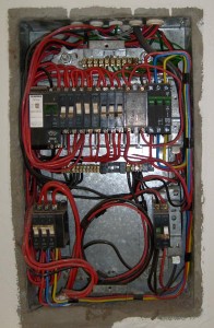
This is the distribution board (DB). The pre-payment meter (bottom left, outside the picture) was wired in later, see the taped wires on the left hand side? The extended wires go down to the meter and then back up to the mains switch at the bottom left.

The red/blue/yellow wires go to the switch at the upper right hand side, and from there to the cable that feeds the garage. That’s the whole point of 3 phase — power to the workshop!
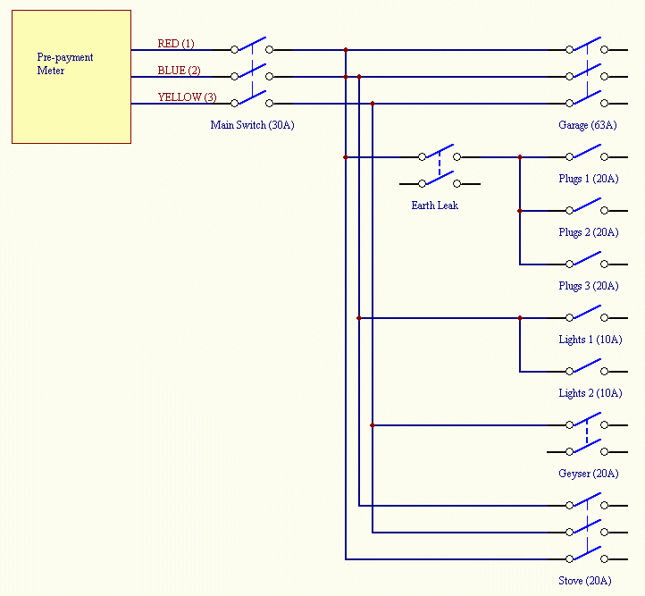
Nicely balanced phases, one phase feeding plugs, one phase feeding lights, and the third phase feeding the geyser.

Only one problem — I much prefer my lights and stove to also be on the earth leak circuit (I got the worst shock of my life unscrewing an Edison screw lightbulb from a metal mounting. The socket was fed via ripcord / flex and obviously the outside of the screw was live. That house still doesn’t have earth leak, but then, I don’t live there any more).

Oh yes, the reason I’m tracing all of this is that I need a circuit for the oven, and two circuits for the jacuzzi (the jacuzzi is wired for a single 40A feed, but I have three 30A circuits only). I have the old stove (3 phase) feed, as well as two plug circuits, the one that used to feed the kitchen, and the one that used to feed the lounge. I’m planning to use the old lounge circuit for the kitchen, and the old kitchen circuit for the fridge and the washing machine / tumble dryer (which will have to live out on the back stoep).

Circuit Current
Oven 14.5A
Dishwasher ~5.5A
Stove (Electric domino) 13A
Geyser 18A
Lights (estimate) 5A
Washing Machine 7A
Tumble Dryer 11A
Jacuzzi Heater 18A
Jacuzzi Pump 6.6A

I played with these values a bit and realised that I’d have to change things around quite a bit to balance the load on the different phases. I also grouped things together logically — we’re unlikely to use the oven and dishwasher at the same time, and even less likely to be in the jacuzzi with the pump on at the same time. So also, the jacuzzi heater can be on the same circuit as the washing machine and tumble dryer, those things are not likely to be used all at the same time… I hope. Comments are of course welcome.

Circuit Red Blue Yellow
Plugs 1 (Bedrooms) 5A
Plugs 2 (Kitchen) 5A
Oven 14.5A
Living Room 5A
Dishwasher ~5.5A
Stove (Electric domino) 13A
Geyser (18A)
Lights 1 (estimate) 2.5A
Lights 2 (estimate) 2.5A
Fridge 5A
Washing Machine 7A
Tumble Dryer 11A
Jacuzzi Heater (18A)
Jacuzzi Pump 6,6A
Total 38A
(20A)
27A 45.5A
(27.5A)

(You’ll notice that the total is not the sum of the column — this is because, for example, the fridge, washing machine and tumble dryer is on one 20A circuit, if it draws more than that the subcircuit will trip).

A total over 30A total is obviously bad, since that would trip the mains. On the other hand, we can learn to not run the jacuzzi heater, the washing machine and the tumble dryer at the same time. The geyser can of course come on at any time, which is why they invented a little black box called a load control relay. I bought a 10A unit — if the stove circuit (stove, jacuzzi pump and dishwasher) draws more than 10A, the relay will make sure the geyser doesn’t come on. If I’m only using one of the stove plates, the stove will draw less than 10A and the geyser will have power.

I might end up fitting a load control relay to the jacuzzi heater circuit as well if things turn out to be a problem.

Weekend kitchen progress

OK, as noted in the previous post, I assembled the unit under the sink.

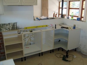
I also turned the units I’d assembled earlier — which go under the stove etc. — on their backs, aligned them and clamped and screwed them together. Because of the corner unit, I could of course only do this for the long side. (OK, I also don’t have the one little 200mm wide unit yet, but that’s besides the point).

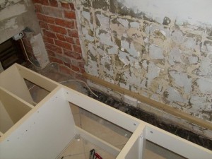
That’s the (15A) socket for the oven. I’m going to run the wires in a pipe down the outside of the kitchen wall, then in via the funny hatch on the left hand side (no idea what its purpose was originally). The wire also continues to the right and through the wall to feed the three plug points in the living room (we removed the pipe feeding those three points when we knocked out the wall between the kitchen and the living room).

With Tanya’s help and much swearing, we got the unit into position (we didn’t get pictures of the bit where I was stuck behind the corner unit and had to climb up and over the wall…)

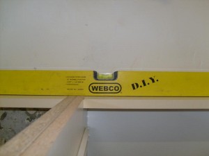
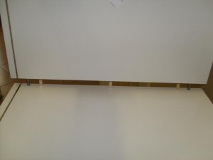
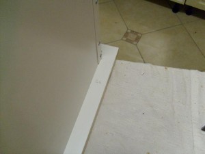
It’s even level. (OK, it’s resting on the batten you can see in the first pic, and that’s level, so it didn’t have much choice… but still).

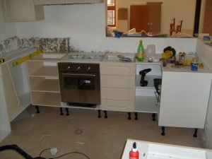
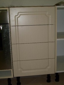
With oven and drawers installed. Looking lekker.

Tanya enjoying some gardening when not required to push, pull and swear at kitchen units.

Assembling kitchen units

I realised that I never posted the details on how the cabinets go together, so this weekend I took some pictures (19 20 thousand words’ worth).

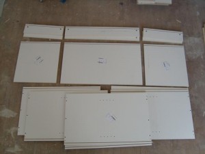
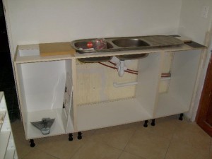
These are the three units which go under the sink (see the floor plan).

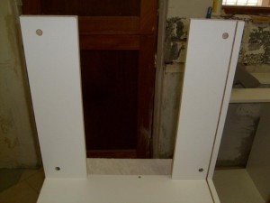
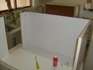
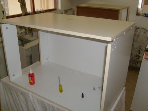
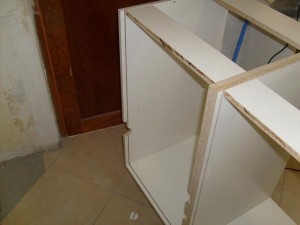
From the top : the two runners which form the top, the bottom, and two sides per unit.

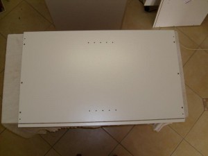
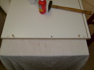
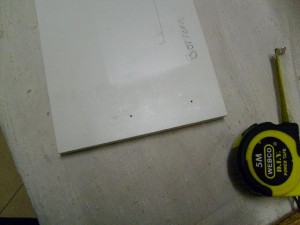
This is the one side. They drilled the centre hole on the left hand side off-center, so I chose that side to be the top (no other choice, really).

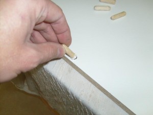
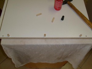
Insert the dowels, three for the bottom end

and two for the top.

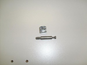
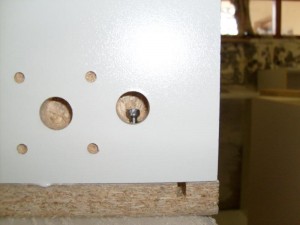
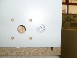
This is the pin and cam that is used to pull the unit together.

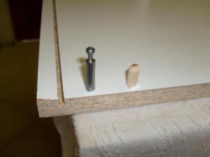
Glue, install.

Pin poking through, cam installed, and cam tightened.

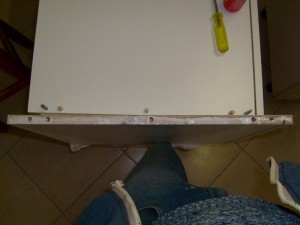
Basically the same thing at the top. I learned the hard way that here it’s important to align things, because the single dowel allows for rotation, and then the top edges come out uneven. So hold the corner square while tightening the cam.

Don’t forget the backing board.

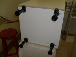
Fit the other side, and the feet.

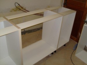
I repeated this exercise three times, laid the three units on their backs on the floor, clamped and aligned the front edges, and screwed the whole thing together, just like Tom Silva shows on this This Old House video.

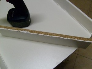
Because of the water and waste pipes, I didn’t fit the backs to the two right-hand units. Which means I had to cut the back bit off the top strips so that I can slide the back in later.

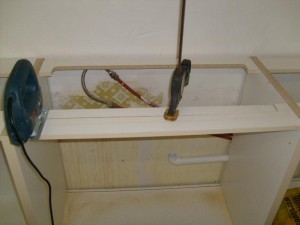
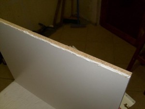
Cutting the hole for the sink. Tip : clamp the bit you’re cutting out so that it doesn’t break and splinter the last bit.

Tanya will have to wear heels to wash dishes — the counter height is 1m.

What the ???

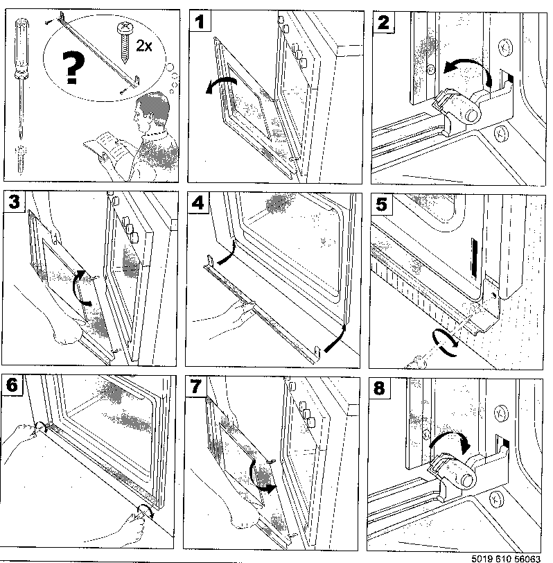
When I unwrapped the oven, I found an L shaped strip of stainless steel taped to the top. Couldn’t figure out what it was for.

So I eventually opened the two packets of hardware that comes with the oven, and found the following instructions :

I read this as “If you’re looking at this bit of metal and you’re wondering WTF?, this is what you need to do”.

Appropriate.

Assembling drawers

The kit from Lansdowne Boards comes with no instructions. I had to figure things out from scratch (OK, so this is not too hard to do. By the fourth drawer I was on a roll. These pics might help you get the drawers right starting with #1).

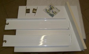
Drawer bottom and back (16mm chipboard), “Metabox” sides, door attachment hardware, and chipboard screws.

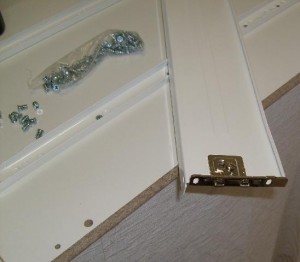
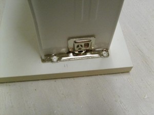
This is how the door is attached to the drawer sides. The two oval screw holes allow for side-to-side adjustment, and the hardware itself allows for a bit of up and down movement using a cam system.
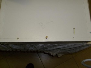
Pick the best side of the drawer bottom and apply a bead of sealant to the long sides (in this pic, the bottom left hand side will form the visible bottom of the drawer).

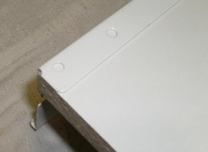
Square up the front of the drawer side with the drawer bottom (In my case this left a bit of an overhang at the rear) and screw it down.

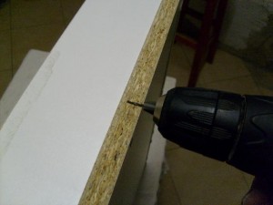
The quick way of lining up screws if you’re not too fussed with the exact dimensions, but you want things lined up.

Three pilot holes (my drawer bottom is 39cm, I drilled holes at 8 1/2. 19 1/2 and 30 1/2 cm.
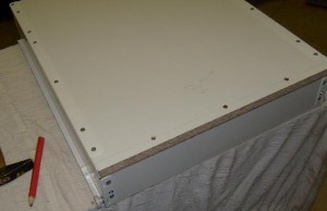
Choose the best side of the back strip and apply sealant to the front three edges.
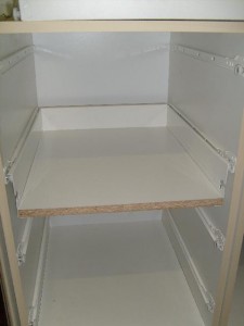
And screw things down (screws are cheap, so I fit them all).

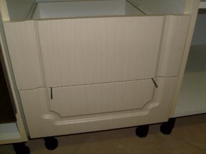
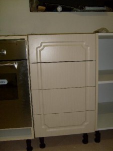
Drawer installed.

I estimated that I needed a 3mm gap between drawers, so I used two 3mm twist drills (“drill bits”, although some people hate the term, like others hate the term “bullet head”) for spacing.

In the end, it turned out that all four drawers were fine with a 26mm spacing. I also lined the sides up, marked the centre of the holes.

I don’t really want to drill right through the drawer door, so I adjusted the depth carefully.

Pilot and screw down.

Before adjustment.

After adjustment. I would probably have to re-adjust once the drawer unit is squared up and fixed to the wall.

Friday night progress.


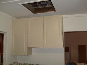
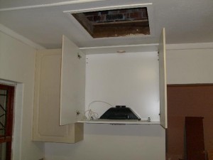
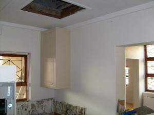
On Friday morning I jigsawed the hole into the bottom of the cabinet and sealed / screwed the extractor fan into place. On Friday evening I hung the cupboard and fitted the side panel and doors. The hole for the extractor pipe almost exactly lines up with the smaller hole Frank put in the ceiling when he fell through.

Of course this means yet another hole in the outside wall, for the extractor pipe (I’m using 120mm sewerage pipe, I have two thirds of a length left over).

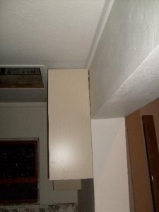
I hid the front two screws for the side panel under the door hinges, and I used the bottom adjustable shelf holes for the two back screws, which means the shelves can’t go at their lowest setting (actually, once the glue has dried, I can remove the two screws at the back, the panel won’t go anywhere).

The wall is… not so straight. But that’s a reality that one has to deal with. This house is actually more square than most.

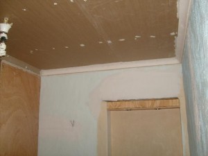
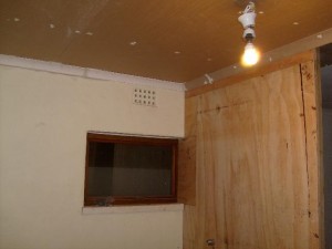
Frank fitted a ceiling to our bathroom. He also fixed the cornices — this is nice, but premature. One should actually tile first, I think.

I’ll have to get a professional tiler to tile our bathroom, Frank’s not that good, and this bathroom must be… nice :-)

When I got home on Friday, the power had tripped. Asked Frank about this, he thinks he might have put a screw through the wires when fitting the cornices. I’ll have to climb up there to have a look *sigh*.

Augustus lê nog voor.

Historically, August is the month of storms and heavy rain in Cape Town. Any rain or storms in June or July is traditionally shrugged off with “August is still coming”.

This year, we had some serious weather in July. If August is indeed worse than July, I shall have to start building an ark.

On the other hand, our lime tree thinks it’s spring (photo using my Samsung S630, which is a handy sub R1k camera. Tanya’s FZ-20 would have done a much better job).

One kitchen cupboard, installed, with side panel and door.

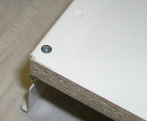
The Lansdowne Boards kit cupboards come with trick pin & cam hardware to hold the thing together without screw heads on the outside. But if you assemble the cupboards like this, with foil panels on the outside, the job would actually be neater without the custom hardware.

Oh, and the eagle-eyed among you will notice four screws in the middle of the panel. Freaked Frank out too. Relax, the next cupboard (visible in bottom left corned, with extractor fan in bottom) will cover those screws. Only the bottom quarter of the panel will be visible.